
[2026] Datum Based Metrology for Freeform Optics
Freeform, aspheric, and off-axis optical components are increasingly used in compact, high-performance optical systems and are typically defined, manufactured, and mounted using mechanical datums. Verifying how the optical surface registers to those datums is essential for accurate iterative processing and for understanding performance in the final assembly.
AOM, together with Zygo and Precitech, developed a demonstration that shows how precision mechanics can engage the mechanical datums of a diamond turned freeform unit under test (UUT) to transfer them into optical references detectable by patterns on a computer-generated hologram (CGH). The Metrology Platform™ (MP) establishes a repeatable mechanical interface to the UUT and incorporates optical alignment targets that decouple alignment degrees of freedom (DOFs), enabling efficient and intuitive testing with a CGH.
Once the test is aligned to the datums, the resulting measurement contains not just the surface figure error, but a quantitative assessment of how the optical surface is registered to its mechanical datums. Using AOM Morpheus™ software, misalignment relative to the datums can be identified, evaluated, and, when appropriate, fit and removed to reflect realistic assembly conditions. Together, the CGH, MP, and software form a streamlined test that supports iterative processing and provides a clear understanding of expected final system performance.
Datums
The freeform UUT is referenced by three mounting datums, as illustrated in Figure 1.
- Datum A consists of three pads on the back surface that establish a plane, setting the Z position and controlling tilt (rX, rY).
- Datums B and C are holes that together define centration in X and Y and control clocking (rZ).

Figure 1. The mechanical datums for the freeform. Datum A constrains Z and tilt. Datums B and C constrain centration and clocking.
This combination of datums fully constrains all six DOFs. When these datums are used in manufacturing, it’s critical to understand how the surface registers to them for any iterative, deterministic turning or polishing. Likewise, if they serve as mounting references in the final assembly, knowing the registration is essential to meet alignment tolerances, especially for snap-together optics or systems with limited adjustability. Leveraging datums during metrology ensures confidence in both manufacturing and assembly.
The Test Components
The MP
To utilize the datums in metrology, they must be translated into optical references detectable by patterns on the CGH. An MP incorporates precision mechanics that engage the datum features. For the freeform datum scheme, a coordinate measuring machine (CMM) can accurately place optical targets relative to the datum references on the MP.
The 6-inch MP shown in Figure 2 is built on an aluminum base compatible with AOM’s FP6 stage. The mirror is located by two pins engaging Datums B and C, while the Datum A pads rest flush against the plate.
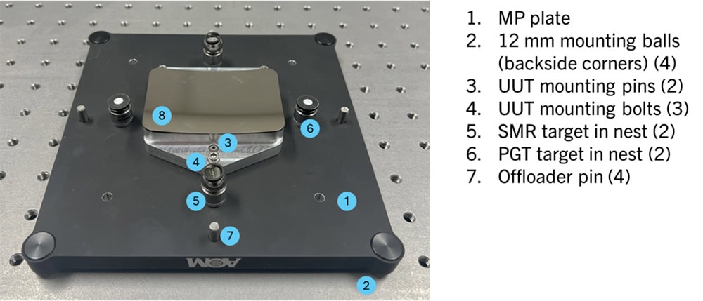
Figure 2. The freeform MP contains locating features to pick up the UUT’s datums and co-aligned optical references.
Four magnetic nests positioned relative to the datum pickups accommodate half-inch sphere-mounted retroreflectors (SMRs) and photogrammetry targets (PGTs). The MP interfaces with the stage via 12 mm magnetic balls in the back corners, along with an offloader pin for added stability, as shown in Figure 3.
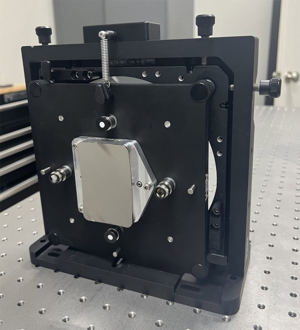
Figure 3. The freeform MP is mounted on the FP6 stage.
The CGH
The CGH is fabricated on a 3-inch substrate and mounted in a cell compatible with AOM’s FP3 stages. The pattern diagram is shown in Figure 4. The central null pattern generates the wavefront for surface testing. Four LFR patterns are included: three sensitive to X-direction displacement and one to Y-direction displacement. These patterns decouple the DOFs of dX, dY, dZ (relative to Datum A), and rZ. Two pairs of PF-V patterns converge to single points for coarse alignment, and a CE-P pattern that targets the UUT vertex provides dZ feedback relative to the optical surface.
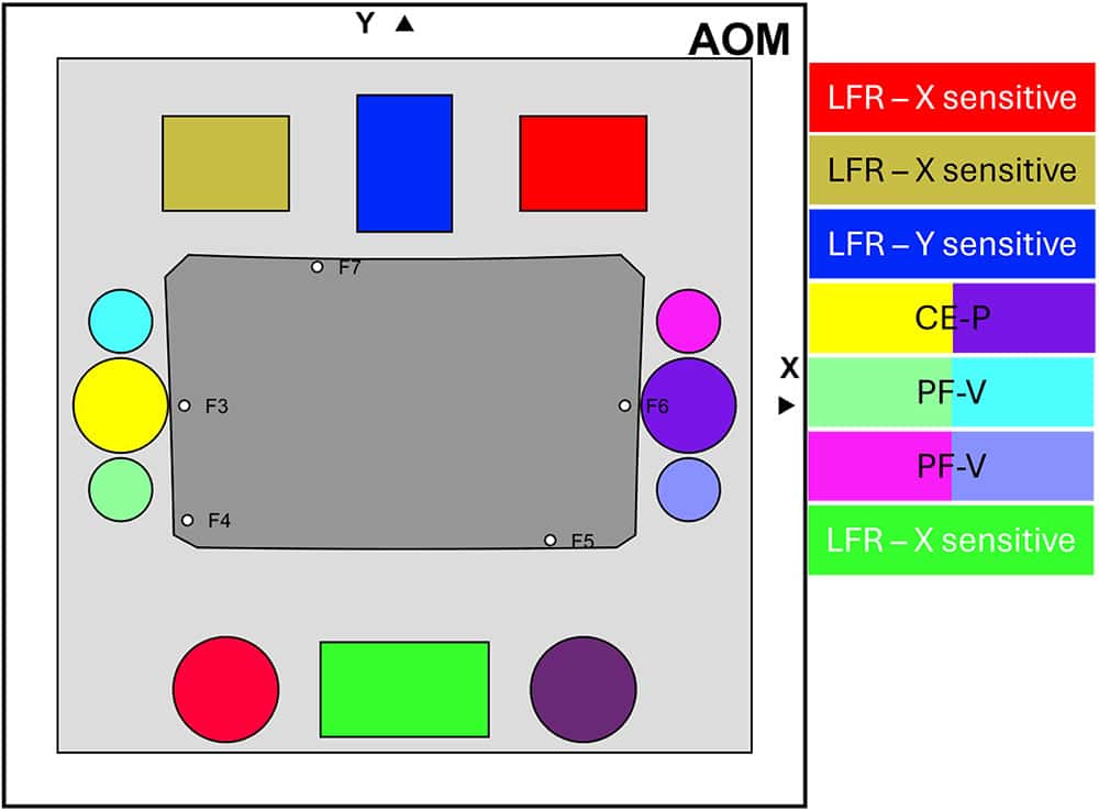
Figure 4. CGH layout for the freeform test.
The LFR patterns target the SMRs mounted in nests on the MP. Three LFR patterns on the null pattern target one SMR, while the single LFR on the opposite side targets the other, as shown in Figure 5.
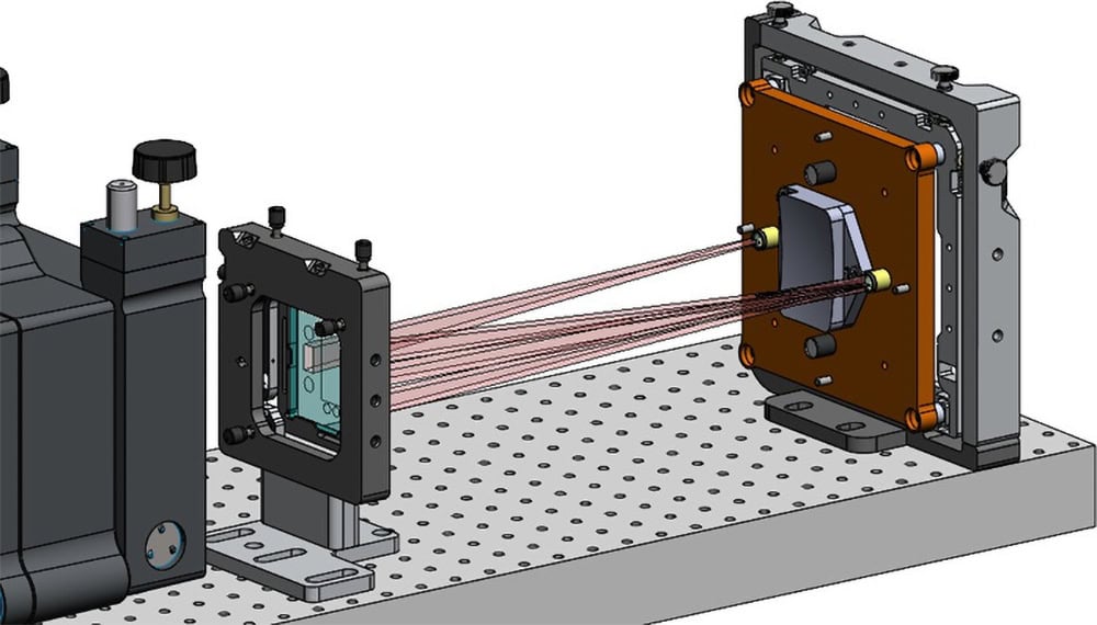
Figure 5. Schematic of the LFR patterns mapping to the SMRs.
The CHG also includes five fiducial marks, labeled F3-7, around the null pattern. These are marked in the interferometer software and used by Morpheus to determine the substrate coordinates of the data.
No specific tilt reference is included in this test. If wedge error were critical to the application, an optical flat reference could be mounted in the platform co-aligned with Datum A and targeted by a CO pattern from the CGH to control tilt DOFs.
The substrate is then mounted in a 3-inch cell that is compatible with AOM stages. During operation, the CGH is mounted on the FP3-Z stage with the +X direction oriented upward, as shown in Figure 6.
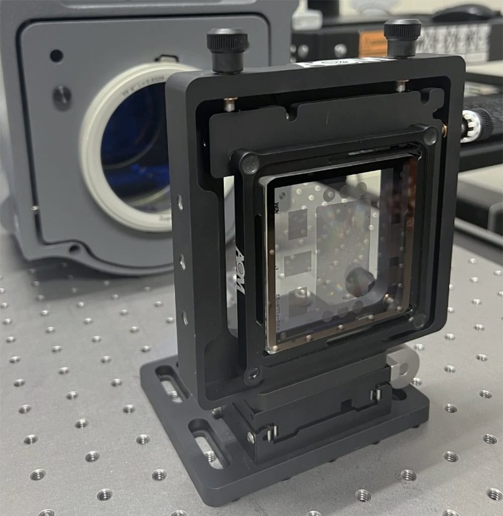
Figure 6. The CGH is mounted on a FP3-Z stage and aligned to the interferometer.
More information about AOM’s alignment patterns can be found here.
Alignment Procedure
This section describes how the CGH alignment patterns are used together to align the freeform UUT to the CGH through the datum references established by the MP.
Each pattern provides feedback on one or more DOFs, allowing the position and orientation of the UUT to be adjusted relative to its mounting datums. For any test design, AOM will recommend an alignment plan that starts with patterns offering the greatest dynamic range and progressing toward the more sensitive patterns as alignment converges. Because the alignment patterns are designed to decouple the DOFs, the order is not strictly constrained, and patterns may be revisited or reordered as needed during the process. During alignment, small amounts of cross-talk between DOFs can arise from the adjustment mechanics of the FP6 stage. As a result, previously aligned patterns may require refinement as other DOFs are adjusted.
The sections that follow outline how each pattern is used to align its corresponding DOFs and how these adjustments fit into the overall alignment strategy.
Coarse Alignment
After aligning the CGH to the interferometer using its retro pattern, the FP6 stage holding the MP is positioned so that each PF-V pair converges to a focus on its corresponding PGT, as illustrated in Figure 7. Once the PF-Vs are focused, alignment can be refined until fringes become visible in the LFR and CE-P patterns.
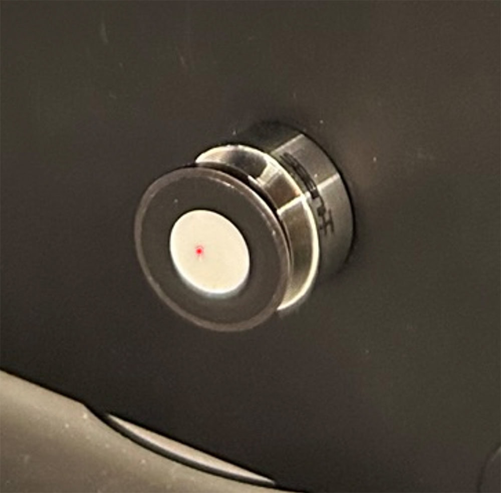
Figure 7. A PF-V pair is focused on the center of a PGT.
Alignment in dX and dY
The LFR patterns are used to align the MP in X, Y, Z, and clocking. Alignment begins with the single LFR sensitive to displacement in Y. Using the fine positioning knobs on the FP6 stage, the MP is adjusted until the chevron pattern collapses into parallel fringes. The chevron orientation indicates the direction the MP must be moved to correct the misalignment, as shown in Figure 8.
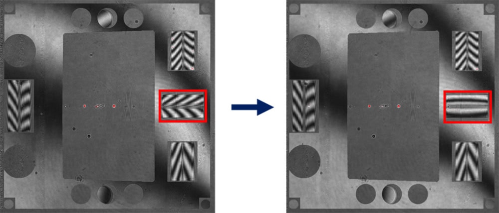
Figure 8. Displacement in Y is aligned by nulling the LFR pattern sensitive to that DOF.
Next, the pair of LFR patterns on the same side of the null that are sensitive to displacement in X are adjusted using X translation. A perfect null for both patterns simultaneously is not achievable since Z position has not yet been aligned; instead, the two patterns are balanced so that their chevrons point in opposite directions with approximately the same number of fringes, as shown in Figure 9.
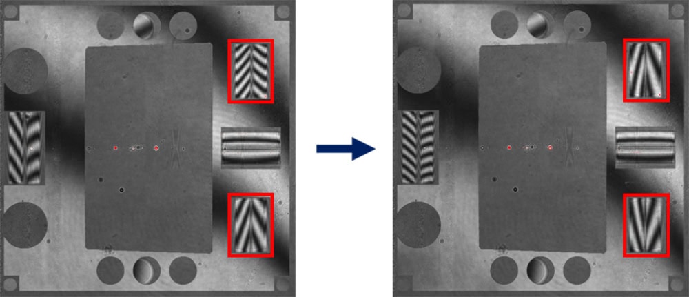
Figure 9. Displacement in X is aligned by balancing the chevrons in the LFR pattern pair sensitive to that DOF.
Alignment in Clocking
Clocking is controlled using the same pair of LFR patterns sensitive to displacement in X on the right side of the null, together with the single LFR on the left side that targets the second SMR. All three patterns will only null simultaneously when the MP is correctly clocked relative to the CGH. Clocking is adjusted until all three LFR patterns show approximately the same number of chevrons, as shown in Figure 10.
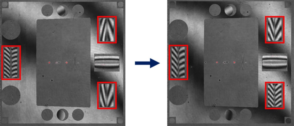
Figure 10. Clocking is adjusted until all three LFR patterns sensitive in the X direction have approximately the same number of chevrons.
After correcting clocking, displacement in X should be re-adjusted to rebalance the LFR pair, as shown in Figure 11.
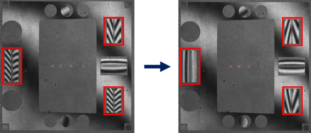
Figure 11. Displacement in X is aligned again by balancing the chevrons in the LFR pattern pair sensitive to that DOF.
Alignment in dZ
At this point, only the LFR pair on the right sensitive to displacement in X requires correction. These patterns target the same SMR from different directions and will both be null only when the SMR is located at the intersection point, corresponding to the correct Z position. The direction of the balanced chevrons indicates how spacing should be adjusted. If the chevrons point away from each other, the CGH and UUT must be moved farther apart.
The FP3-Z stage holding the CGH provides more accessible Z adjustment than the FP6 stage supporting the MP. Because the input wavefront is collimated, the interferometer to CGH spacing is not critical, so CGH to UUT spacing adjustment is typically performed on the CGH stage. In Figure 12, all LFR patterns are aligned.
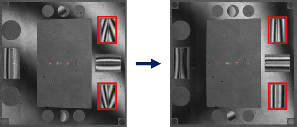
Figure 12. Spacing is adjusted until the LFR pair is nulled.
Alignment in Tilt
The final DOFs are tip and tilt. This test did not specify a wedge tolerance, so tilt is removed using the null pattern. If no fringes are initially visible, the CE-P pattern can be used for coarse adjustment by centering the return within the pattern. Once centered, fringes will appear in the null pattern, as shown in Figure 13, and tilt can be further refined using the null.

Figure 13. Tilt is coarsely adjusted using shear of the CE-P.
Data Processing
With alignment procedure complete, the fiducial marks should be marked in the interferometer software. Then, the null pattern can be masked and measured, with the understanding that the CGH is aligned to the mechanical datums of the UUT to within the uncertainties of the alignment patterns. The data are then exported and processed in Morpheus using the corresponding .cgh file. The Alignment Correction tab, shown in Figure 14, reports how the measured surface is misaligned relative to the defined datum reference frame.
For this freeform surface, the “X-Decenter” and “Clocking” misalignment modes are nearly degenerate, which prompts a warning from the software. In such cases, it is up to the user to determine which mode is most appropriate to fit based on the intended post-processing workflow or the constraints of the final mounting assembly.
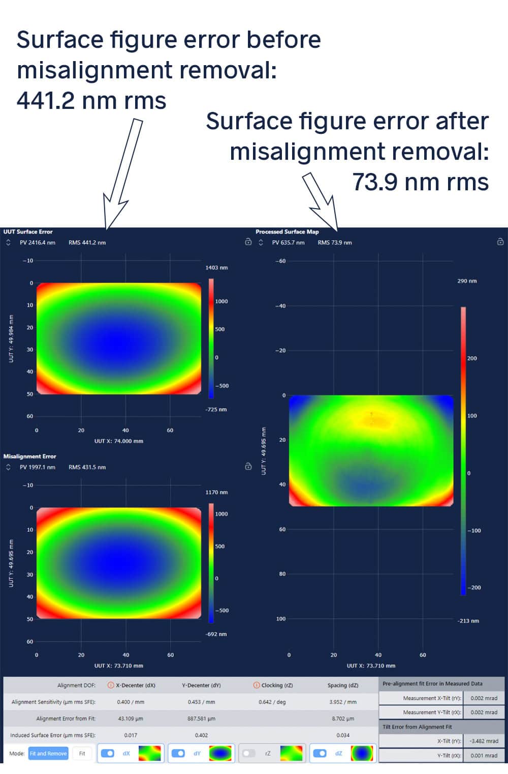
Figure 14. The Alignment Correction tab within Morpheus showing the fit and removal of misalignment error from the data.
When adjustability is available in the final assembly, it is often advantageous to disable the DOF that is least controllable or that offers the smallest dynamic range. For example, if the final assembly allows for dX adjustment but not clocking, disabling the “Clocking” alignment mode provides a more practical and representative fit. A deeper discussion on using the Alignment Correction feature in Morpheus can be found here.
In this example, Morpheus predicts that mounting the part strictly according to its mechanical datums would result in a surface figure error of 441.2 nm rms. When adjusted according to the “Alignment Error from Fit” values, the effective surface figure error is reduced to 73.9 nm rms, illustrating the impact of combining datum-based metrology with controlled alignment in the final assembly.
This demonstration shows how freeform surface metrology can be directly referenced to the mechanical datums that define how a part is manufactured and assembled. By engaging those datums with precision mechanics and translating them into optical references, the CGH enables easy alignment by decoupling DOFs. Morpheus provides quantitative insight into how the optical surface, once aligned, registers to its datums and how misalignment impacts performance. This metrology approach results in a reliable understanding of the test optic including its datums, opening up reliable deterministic processing and datum-registered optical assemblies.