
CGH Test Alignment Correction with Morpheus
Morpheus™ is AOM’s cutting-edge software platform for processing CGH optical surface figure metrology results, designed to deliver highly accurate surface figure analysis. Alignment Correction is the final step in the processing sequence and the most powerful tool in the workflow. By effectively quantifying and removing misalignment aberrations, it ensures precise and consistent surface figure data, making it an essential step for complete surface analysis.
As an illustrative example we will examine a freeform surface test designed and measured at AOM. The test geometry and CGH layout are shown below. The Unit Under Test (UUT) is a round-aperture freeform surface with mechanical datums defined by a back plane, a center hole, and a slot. For this test, AOM developed a custom Metrology Platform™ (MP) that references all three datums and includes coaligned sphere-mounted retroreflector (SMR) targets for use with line focus (LF) patterns in the CGH. The configuration of these LF patterns enables alignment in X and Y relative to the center hole and clocking relative to both the center hole and the slot. A catseye pair (CE-P) alignment pattern provides accurate feedback for the spacing between the CGH and UUT.
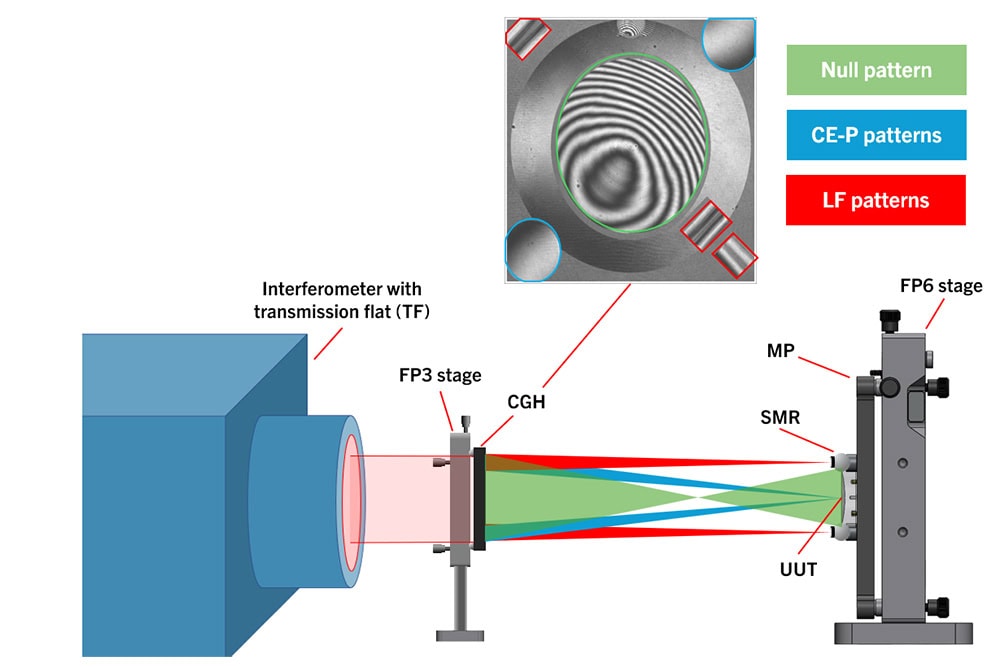
Test geometry and CGH layout for a freeform surface test.
How does Morpheus Alignment Correction work?
During the design of a CGH test, AOM calculates the unique aberrations introduced when the UUT is perturbed relative to the CGH in its relevant degrees of freedom. These misalignment-induced aberrations are then encoded into the corresponding .cgh file.
In the freeform example above, the UUT has six independent degrees of freedom. The resulting misalignment modes are shown below in UUT space with tilt compensation.
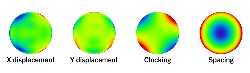
The resulting misalignment modes for the freeform example above.
The misalignment modes shown above are specific to the CGH and UUT pair. They should not be confused with pure Zernike terms, which, in general, do not accurately represent the true misalignment modes of a freeform system. This distinction underscores a key limitation of removing standard Zernike terms: the method leaves behind higher-order contributions of the misalignment modes in the surface map, making this method insufficient for accurately handling misalignment errors.
After correcting for mapping distortion, Morpheus fits the alignment error across each relevant degree of freedom, as shown below. Morpheus software provides an option to subtract the fitted misalignment modes from the measurement data, effectively isolating the true surface figure error.
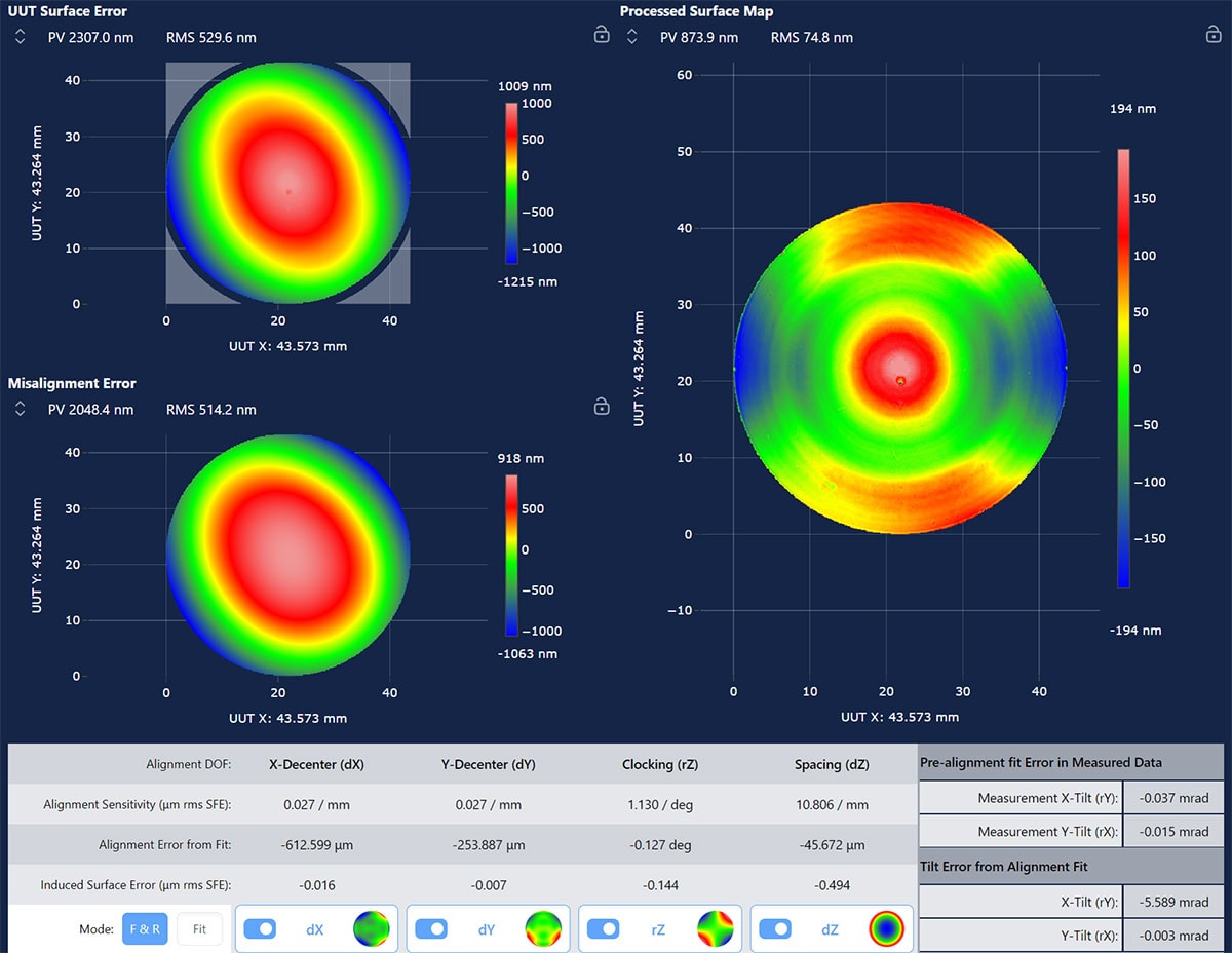
Morpheus Alignment Correction view showing input data map (top left), the fit of the alignment error across each relevant degree of freedom (bottom left), and the resulting surface figure error map with misalignment aberrations subtracted from the input data (right).
How to use Morpheus Alignment Correction
There are several ways to use and apply the misalignment correction data. The best approach depends on the UUT specifications and how the UUT will be mounted in its final assembly.
Remove all misalignment
One of the most straightforward applications of this feature is to remove all misalignment contributions for the relevant degrees of freedom. This approach is recommended when the UUT’s alignment can be adjusted in its final assembly. In this case, Morpheus provides an estimate of the best possible surface performance, assuming perfect placement of the UUT.
Walk the part into alignment
In cases where a numerical correction is not preferred, the “Alignment Error from Fit” output can be used to iteratively adjust the UUT’s position relative to the CGH. By applying the reported misalignment corrections and repeating the measurement, the UUT can be positioned incrementally to within the mechanical capability of the alignment stages.
Understand the surface registration
If the surface test includes alignment patterns that receive feedback from a target positioned relative to the UUT datums, the misalignment fit feature can quantify how well the part is registered to its defined datums. The freeform example above incorporates alignment features that constrain the datums in X, Y, and clocking. The Morpheus screenshot above shows the processed data from a measurement taken with all datum references aligned. These results indicate that the surface is decentered from the center hole by -613 µm in X and -254 µm in Y and is clocked by -0.13° relative to the hole/slot combination.
How good is Morpheus Alignment Correction?
We can evaluate the performance of Morpheus’s misalignment correction feature by analyzing its accuracy and reproducibility. By examining a series of measurements of the same test with different misalignments, we can assess how reliably the software identifies and removes misalignment errors for confident surface figure measurements.
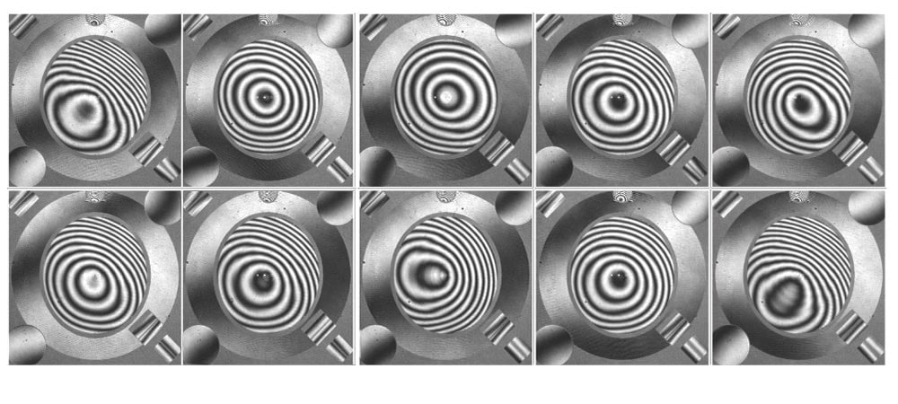
A total of 11 measurements were taken with our example freeform test at different alignment positions. Measurement 0 represents a well-aligned reference. X, Y, and clocking are aligned according to the LF (line focus reference alignment) patterns. Z is aligned based on the CE-P (catseye pair) alignment pattern, and tilt is nearly corrected using the null pattern. The remaining measurements exhibit significant misalignments in one or more degrees of freedom, though the fringes remain resolvable. The interferograms for each measurement are shown below.
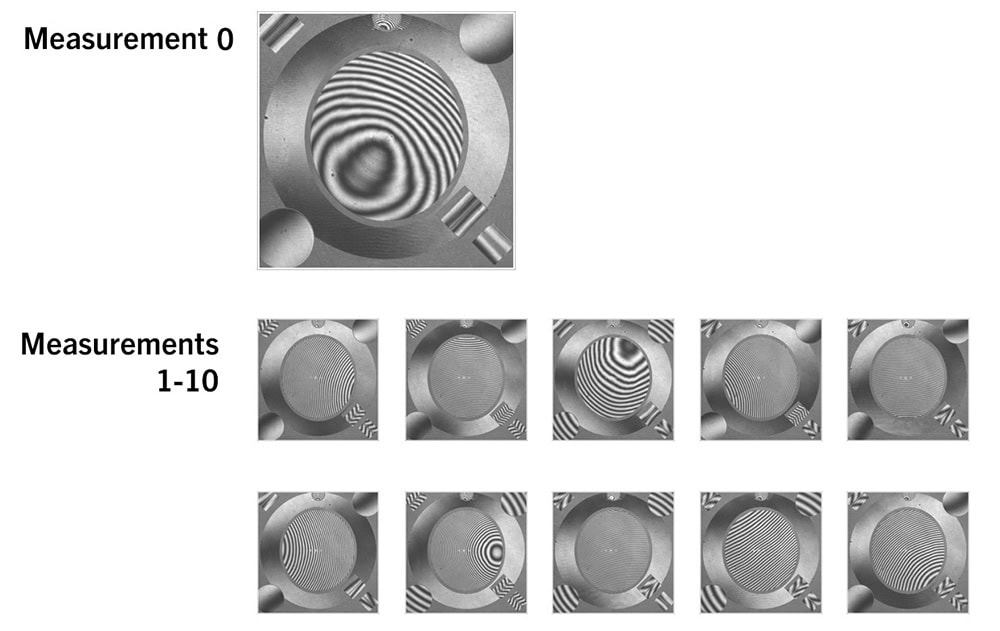
Eleven measurements taken with freeform test at various alignment positions.
For comparison, we’ll first examine how the data appear after standard low-order alignment mode removal – piston, tip/tilt, and power were fit and removed from the phase measurement using the interferometer software. The corresponding surface figure error maps are shown below. They are plotted on the same color scale and exhibit noticeable variations. These differences are artifacts of improper removal of the varying alignment modes between the UUT and CGH. The average RMS error across all measurements is 71.4 nm, with a standard deviation of 10.2 nm, which indicates low accuracy and high uncertainty in the measurement.
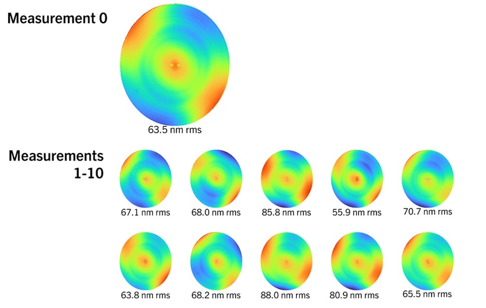
Variability between Zernike analysis of the eleven measurements indicates low accuracy and high uncertainty in the measurement.
Next, the original data are processed through Morpheus, where all misalignment modes are fit and removed using the perturbation analysis provided by AOM. The resulting surface maps, which are shown below using the same color scale, demonstrate significantly improved repeatability. The average RMS error is 79.2 nm, with a reduced standard deviation of 5.4 nm. Note that some visible variation appears near the center of the part, which is attributable to minor ghosting effects present in the center of the null pattern in the fringe maps.
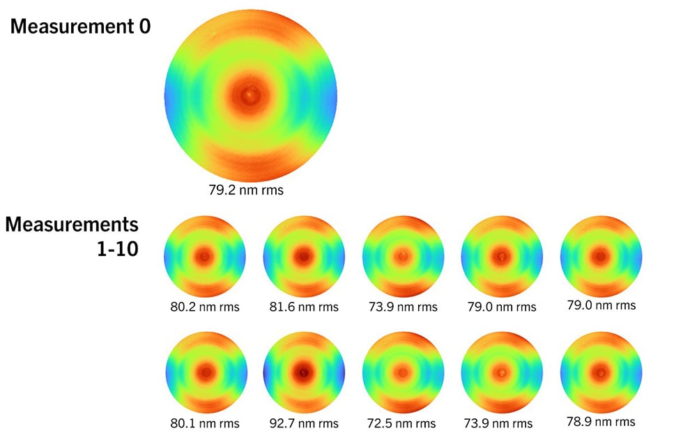
Morpheus analysis of the eleven measurements demonstrates improved consistency.
The previous study provided insight into significant misalignment error in the interferogram. To evaluate repeatability under more practical conditions of slight misalignment of the UUT to CGH, ten measurements were taken with the MP well-aligned to the CGH. Between each measurement, the UUT was unmounted, remounted, and realigned. The average RMS of the processed maps was 80.1 nm, with a standard deviation of just 0.7 nm, demonstrating excellent reproducibility.
Ten measurements demonstrate excellent repeatability of the alignment method under practical conditions.
Morpheus Alignment Correction provides exceptionally accurate and repeatable measurements with CGHs. It should be a key part of any surface figure test workflow involving CGH-based metrology. The deterministic fit unlocks the true surface of the UUT, helps refine alignment, and assesses how well the surface registers to its mechanical datums. Morpheus incorporates deterministic alignment correction directly into the processing workflow, enabling reliable surface measurements and reducing complexity in CGH metrology.