
Line Focus Reference Alignment Patterns (LF)
| Name & IDs | Symbol | Typical Target Used | DOF and Sensitivity | Description |
|---|---|---|---|---|
| Line Focus (LF-H, LF-V, LF-R, LF-T) |  | Corner Cube, SMR | Fine alignment of dX OR dY; (Pairs of patterns can also align dZ and clocking) | Projects a line focus to specified retroreflector alignment target. Provides alignment in a single degree of freedom (perpendicular to the line). LF-H, LF-V, LF-R, and LF-T specify Horizontal, Vertical, Radial, or Tangential. |
Line Focus Reference (LF) Alignment Patterns create a line focus at the center of a Corner Cube (retroreflector) target.
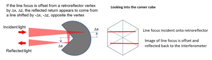
LF patterns measure the deviation of the retroreflector position with respect to the projected line in the direction perpendicular to the line.
As long as the light is illuminating the corner cube, the fringe pattern is insensitive to a shift along the direction of the line.
When the line is focused exactly on the retroreflector vertex, the reflected light returns to the CGH creating a null fringe.
AOM adds a few fringes of tilt to this null state to aid in the visual alignment of fringes: Instead of obtaining a null interferogram, you instead make the “V” fringes parallel. The V fringes also help indicate the direction of misalignment.

Multiple LF patterns can be arranged on a CGH in combination with multiple retroreflector targets to assess freeform UUT misalignment in all degrees of freedom.
A video illustrates dY alignment of a LF pattern. Horizontal tilt fringes are reduced until only vertical tilt fringes remain. The objective is to make the remaining vertical tilt fringes parallel.
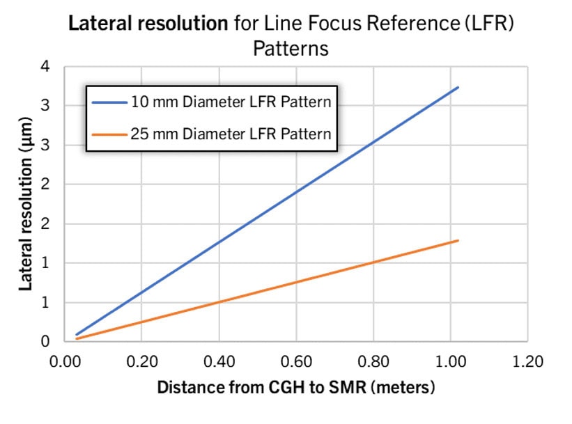
Lateral Misalignment
The sensitivity of a LF pattern to lateral misalignment depends on pattern size and distance to retroreflector target. A table of typical values is shown below.
Axial Misalignment
Two LF patterns which are laterally separated on the CGH and target a single target can be used to assess axial (distance) alignment to the target.
- Use parallax effect to measure z offset
- Shift of dz causes each LFR to shift laterally

A video demonstration of dZ alignment with LF patterns is shown below. The patterns outlined in red are assessed to evaluate axial alignment.
The sensitivity of a LF pattern to axial misalignment depends on pattern size, pattern separation on CGH, and distance to retroreflector target. A table of typical values is shown below.

Clocking Misalignment
Two LF patterns, targeting two retroreflector targets that are laterally displaced, can be used to assess clocking misalignment to the targets. The concept is shown in the figure below.

A video demonstration of clocking alignment with LF patterns is shown below. The patterns outlined in red are assessed.
- The top two patterns assesses dX of a target located in +Y
- The bottom pattern assesses dX of a target located in -Y
- When the V-tilt of top patterns and bottom patterns point in opposite directions, there is clocking misalignment of the reference targets.
Click here for a summary table of all AOM alignment patterns.