
The Importance of UUT Alignment
Why is it important to ensure that your test optic is aligned in a CGH test?
To understand this, we must understand how freeform alignment differs from alignment of a sphere.
Spheres are straightforward to test.
- Shape is described by one number: Radius of Curvature (flats have ∞ radius)
- Position is fully described with one (x,y,z) location
- Spherical wavefront propagates as sphere, changing only radius of curvature
- The sphere has degenerate alignment modes, making it easy to align and is tolerant of misalignment (both in the test and in operation)

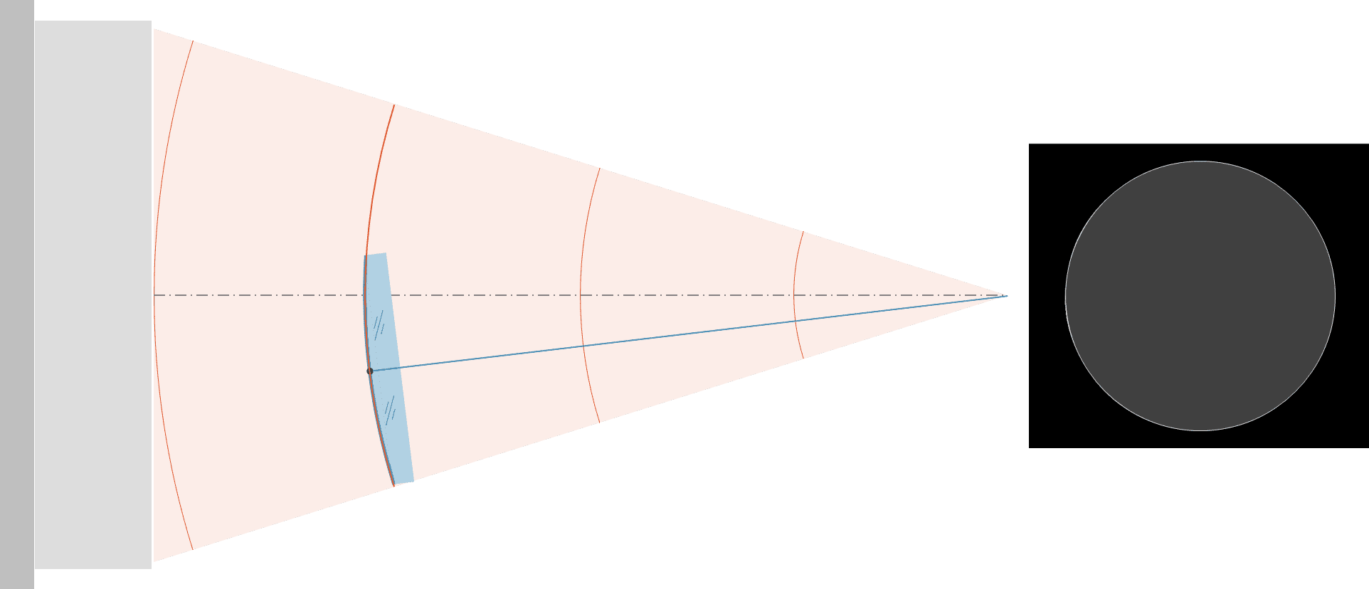
Top: Sphere decenter misalignment manifests as tilt in the interferogram. This misalignment can be fully compensated with either tilt or decenter of the sphere.
Bottom: Tilt alignment of the decentered sphere, resulting in a null interferogram.
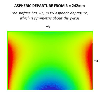
A freeform optical surface, on the other hand, is composed of:
- Base sphere, most of the sag and slope come from this
- Aspheric departure on top of the base sphere
Misalignment of aspheres and freeforms cannot be perfectly compensated with other alignment degrees of freedom.
This directly impacts measurement accuracy and can lead to erroneous manufacturing feedback.
Below are three examples of different freeform surfaces, described by the Zernike Standard coefficient basis. The surface figure error when all 3 optics undergo the same X decenter misalignment is shown on the top row, and the residual surface figure error after compensating with other alignment degrees of freedom (tilt, clocking) is shown on the bottom row.
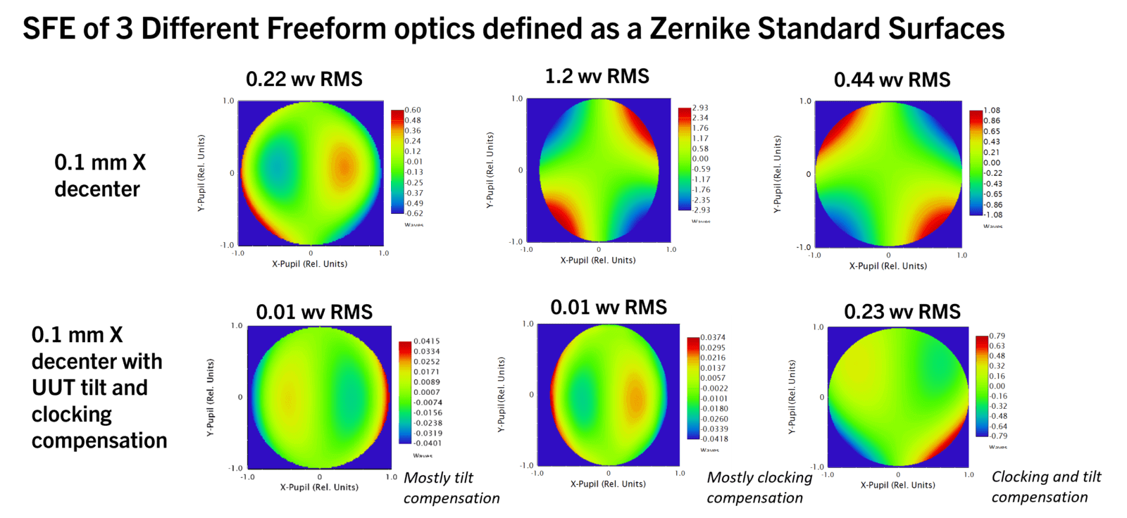
What is clear from this comparison is that the misalignment-induced surface figure error varies wildly (both in RMS value and in the signature in the maps) depending on surface prescription. What also varies significantly is the ability to compensate dX misalignment error with other test optic alignment modes. For example, the freeform in the center has the largest initial surface figure error (1.2 waves RMS), but nearly all of this error can be compensated with clocking of the UUT. On the other hand, the freeform on the right has an intermediate amount of SFE (0.44 waves RMS), but only half of this error can be compensated with clocking and tilt of the UUT.
As opposed to a spherical surface, in the case of a freeform, it is impossible to completely compensate for one misalignment degree of freedom using a different alignment degree of freedom.
AOM Alignment Solutions
What can be done to address this challenge? It is important to have an independent check of test optic alignment that relates to mounting datums of the UUT. AOM has developed several test optic alignment strategies that allow the metrologist to ensure UUT-to-CGH alignment from course to fine in all degrees of freedom.
To reduce test optic misalignment, CGHs can be designed with specialized Alignment Patterns that target the UUT and co-located reference targets on a Metrology Platform.
Additionally, Morpheus™ data reduction software from AOM can fit and optionally subtract freeform misalignment modes from test data.