
4. Substrate Correction
Overview
The first step in the Morpheus™ processing pipeline is to correct any small errors attributable to the CGH substrate from the UUT measurement data, and to transfer the measurement data to the substrate domain, as opposed to the detector domain which it was read in from. Substrate errors may come from small imperfections in the surface figure or material properties of the CGH glass. These errors are static, stable, and present in all measurements taken with the CGH, which means they can be measured and corrected in the test data. AOM measures the transmitted wavefront error (TWE) of each CGH during the assembly and test process at the factory. The substrate TWE map is saved in the .cgh file along with a set of fiducials, which are physically and precisely located on the CGH substrate, that establish the location and orientation of the CGH substrate error map.
The CGH substrate error is removed from UUT measured data in Morpheus™ by first utilizing the fiducials to transfer both maps to the CGH substrate domain, to assure both maps are in the same domain. This process additionally captures distortion which may arise between the CGH substrate the detector. Such distortion may arise from mapping error arising from a fast F/# transmission sphere, anamorphism due to high tilt of the CGH substrate relative to the interferometer optical axis, and more. By utilizing marked and known fiducial positions, Morpheus™ can accurately capture this mapping distortion and correct for it.
Then, the CGH substrate correction map is directly subtracted from the measurement. Finally, Morpheus™ applies a mask, representing only the null region on the substrate, to assure that only valid data is included for processing. The mask is precisely defined as the null region, and is positioned relative to the fiducials, which define the substrate coordinate frame.
Morpheus™ can also accept a user-supplied substrate TWE measurement in place of the factory measurement. If you choose to provide your own substrate TWE measurement, you must provide a measurement that is taken with the same interferometer and setup as the measurement data you are processing, and, you must have marked the fiducials in the substrate TWE measurement as described in the Preparing Metrology Measurements for Morpheus section of this manual. Please contact AOM to obtain detailed instructions for creating your own substrate TWE measurement.
Substrate Correction with AOM’s Measurement
By default, Morpheus™ will use the substrate error measurement from the .cgh file provided by AOM. When you process a measurement in Morpheus™, the substrate error will be subtracted from your UUT measurement data. This is accomplished by first determining the relationship between the fiducials in the substrate error map and the fiducials in the UUT measurement map. The substrate error map, and the test measurement data, are then transformed to align its fiducials to the ideal CGH substrate domain, defined by the ideal fiducial coordinates on the CGH substrate. The CGH substrate error map is then subtracted from the UUT measurement data pixel-by-pixel.
Subtracting CGH Substrate Error with Your Own Measurement
After you have loaded your CGH file, the TWE Source field in the application will show “AOM Provided”. To load your own substrate TWE measurement, select the folder icon next to this field, as shown below.
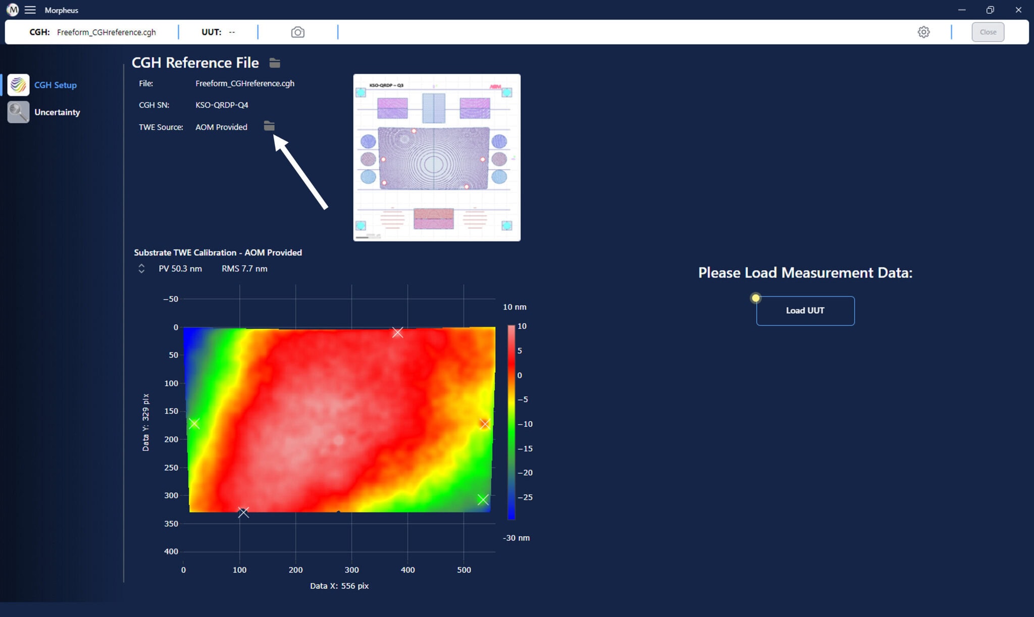
You will be prompted to find and select your own substrate TWE measurement file, which must be a .dat or .datx file with the fiducials marked. Once uploaded, you will see the TWE Source change from “AOM Provided” to “Customer Provided”.
Viewing the Results
Once the substrate error has been subtracted from the UUT measurement data, you can view the results by clicking on the ‘Substrate Correction’ button in the Data Processing panel of the Morpheus™ window. See below for an example of what the results should look like.
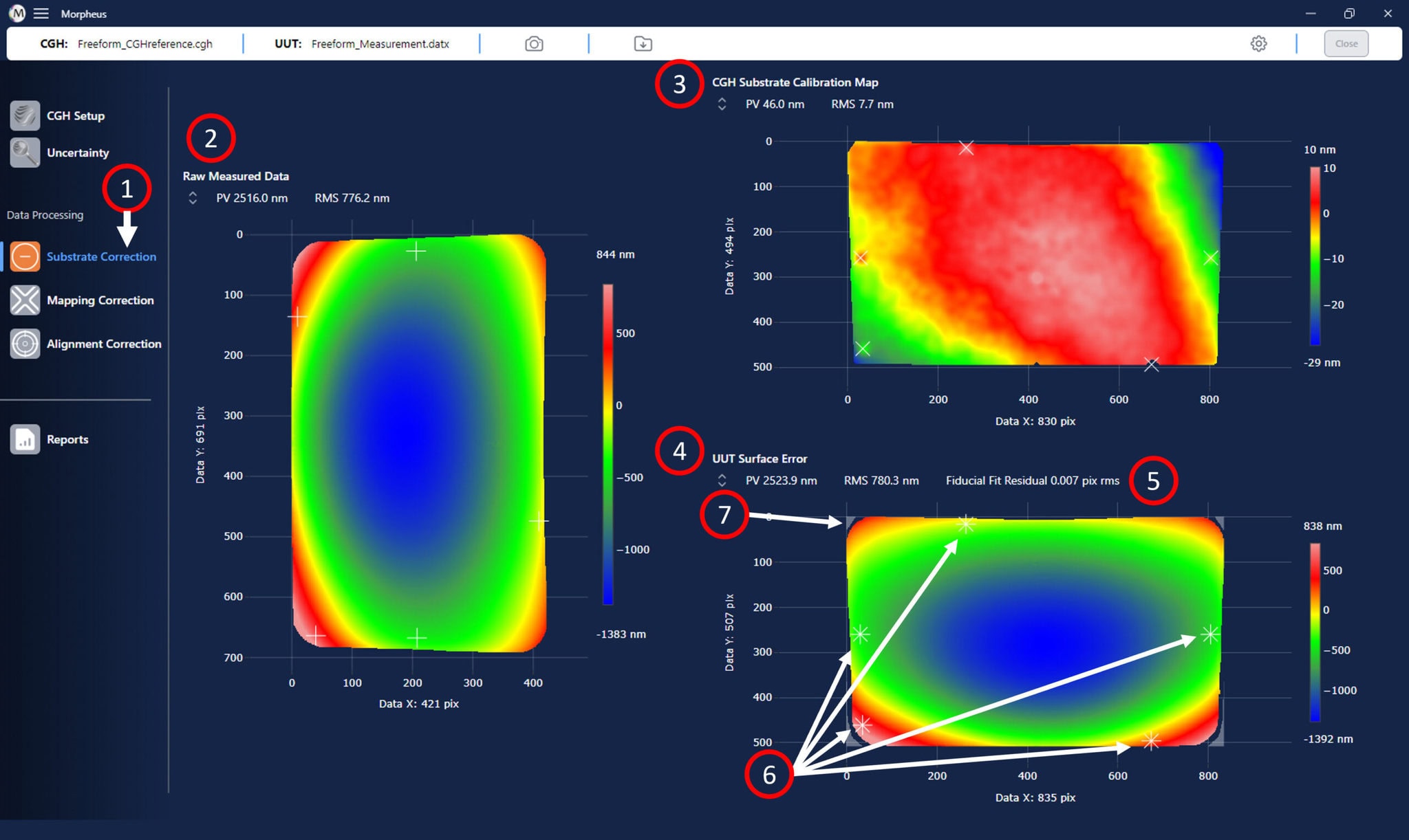
The results of the CGH substrate correction are shown in the main window of Morpheus™:
- Click on the ‘Substrate Correction’ button to view the results from this data processing step.
- The input UUT surface error map is shown in the left panel of the Morpheus™ graphics window.
- The CGH substrate correction map, after being transferred to the CGH substrate domain, is shown in the top right panel of the Morpheus™ graphics window.
- The difference map, after both the test optic raw measurement data and substrate correction map have been transferred to the CGH substrate domain, which represents the UUT surface error with the CGH substrate error removed, is shown in the bottom right panel of the Morpheus™ graphics window.
- The fiducials from both the CGH substrate error (“X”) and UUT measurement maps (“+”) are overlaid in the difference map.
- The fit residual between the adjusted CGH substrate error fiducial locations and the UUT measurement data fiducial locations provides a metric for the quality of the fiducial marking. AOM recommends a fit residual value less than 1% of the total pixel extent of the UUT data to indicate a good marking of fiducials.
- The null region mask, which includes data in the null region of the CGH substrate (clear), and excludes data outside of that region (light gray) can be seen on the processed data.
Next Steps
You are now ready to proceed with correcting the mapping relations between the UUT and the CGH. Please see the Mapping Correction section of this manual for details on how to correct the mapping relations between the UUT and the CGH.