
2. Loading Data into Morpheus™
When you first open Morpheus™ you will need to load a .cgh file along with a UUT measurement data file that both correspond to the same CGH test. See below for how to load each file type.
What is a .cgh File
A .cgh file is a digital representation of your specific CGH and test setup. The file contains key data regarding the as-built CGH device, as well as the test geometry, tolerances, uncertainties, and more. This file enables the advanced CGH-specific data processing features in Morpheus™. If you do not already have a .cgh file for your CGH, please contact AOM.
Loading a .cgh File
To load a CGH file, click on the folder button in the CGH Reference Data panel of the Morpheus™ window.

This will open a file dialog where you can select your CGH file. Once you have selected your CGH file, click ‘Open’ to load it into Morpheus™. For this guide, we will be using the “Freeform_Rectangular_Optic.cgh” file included with Morpheus™. See below for what your screen should look like if you loaded the “Freeform_Rectangular_Optic” file.
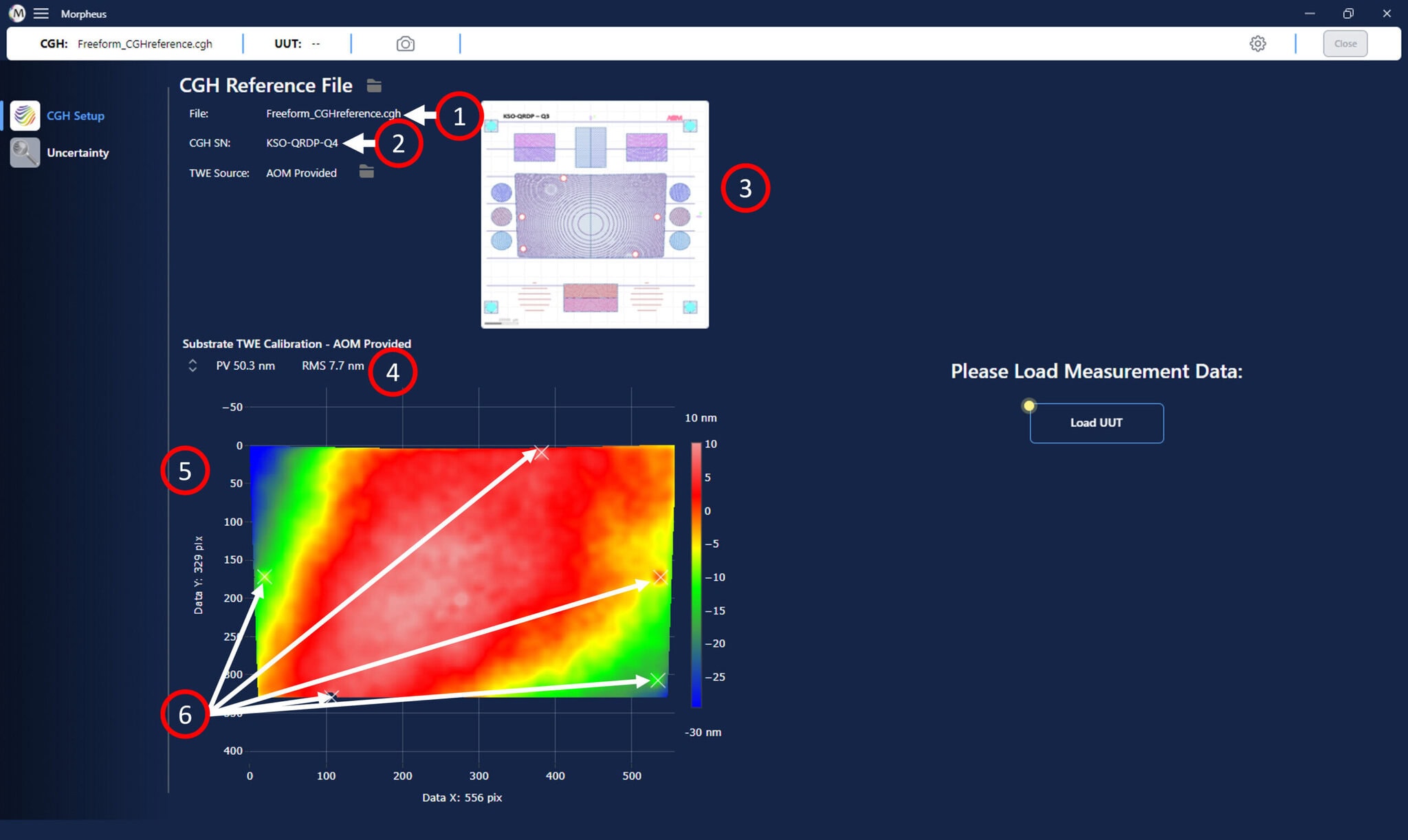
There are several important pieces of information now presented to you from the loaded CGH file:
- The .cgh file name is displayed in the top left corner of the Morpheus™ window.
- The serial number for the specific CGH device associated with the .cgh file is displayed just below the CGH file name in the Morpheus™ window.
- A CGH pattern layout diagram is shown in the upper left of the Morpheus™ window.
- The map statistics, including the Peak-to-Valley (PV) as well as Root-Mean-Square (RMS) of the map are shown above the map.
- The CGH substrate error map as measured by AOM is shown in lower left of the window.
- The fiducials, as marked during the fabrication and quality control process at the AOM facility when measuring the substrate error map are marked with “X” symbols on the map.
Loading a Measurement Data File
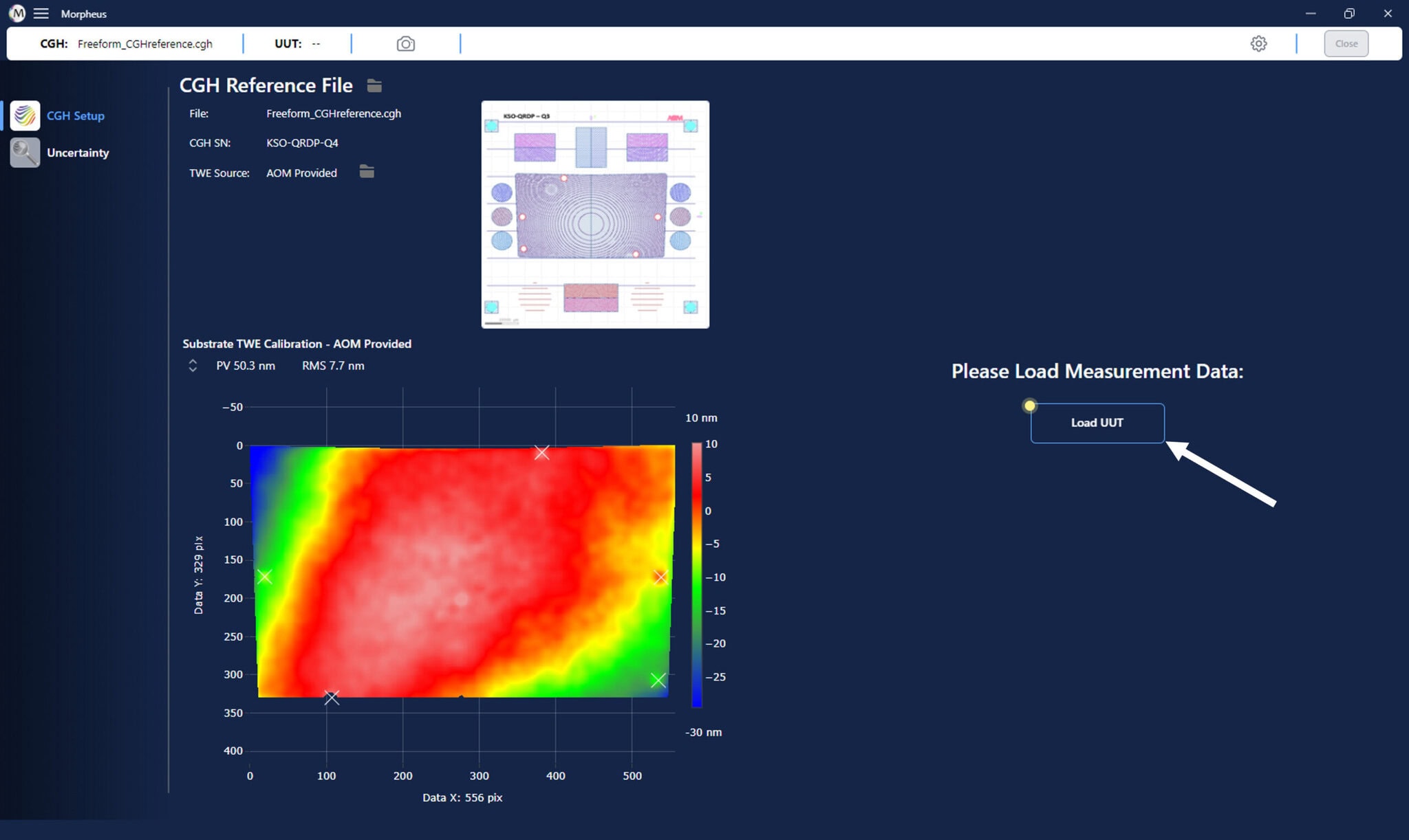
To load a measurement data file for the unit under test, click on the folder button in the UUT Measurement Data panel of the Morpheus™ window, as shown below.
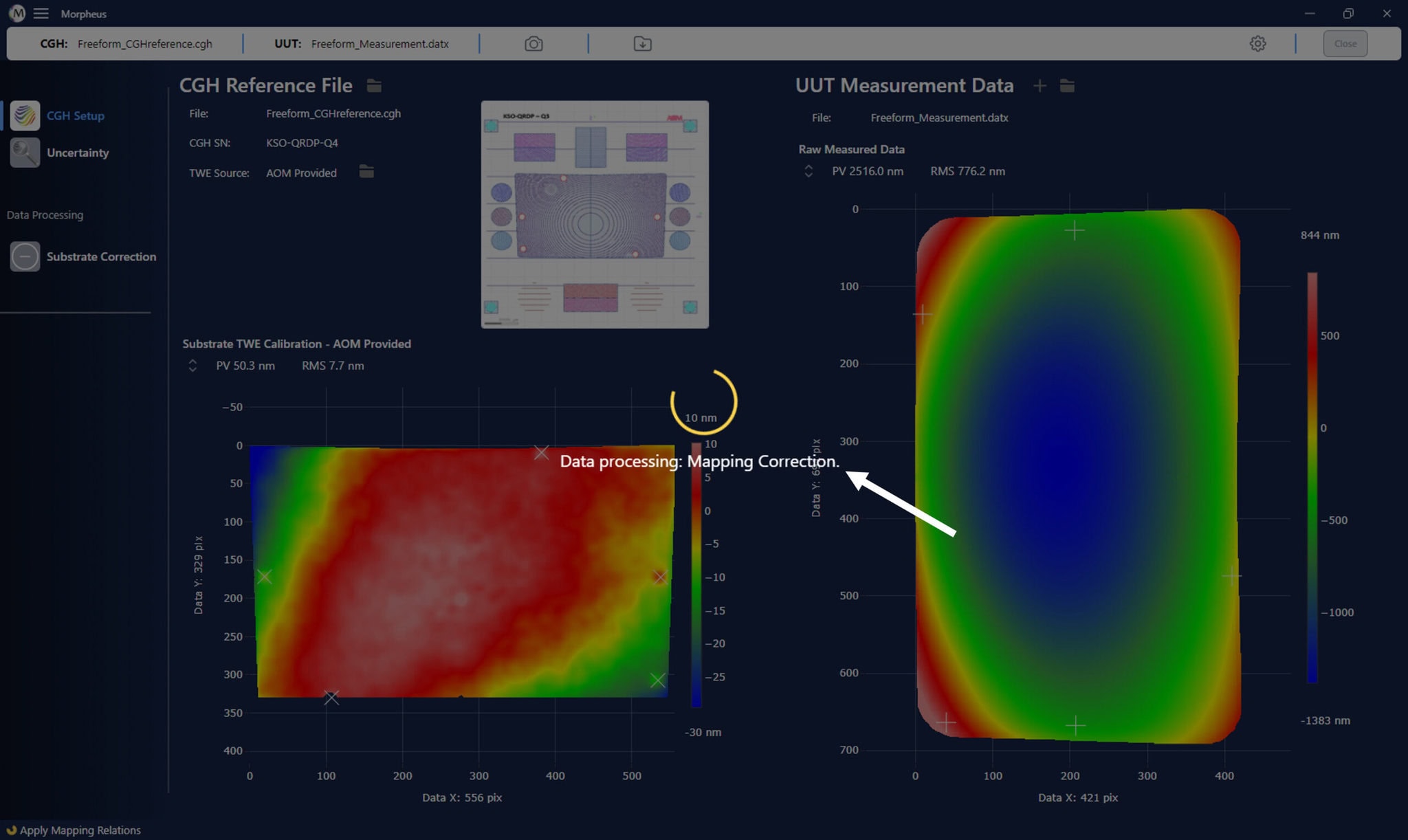
This will open a file dialog where you can select your measurement file. Once you have selected your file, click ‘Open’ to load it into Morpheus™. We will continue with using the “Freeform_Rectangular_Optic.datx” sample file included with Morpheus™. See below for what your screen should look like if you loaded the ” Freeform_Rectangular_Optic ” file. By default Morpheus™ will auto process the data, during which you will see a processing screen like the one below.
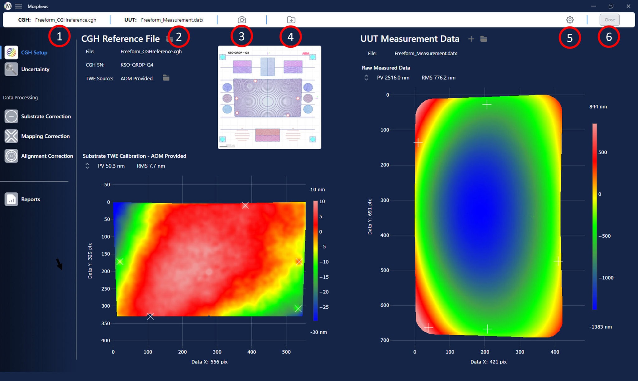
After processing has finished, which should take no more than a minute or two, you can see all of the details of the loaded measurement file. See below for what your screen will look like with the ” Freeform_Rectangular_Optic ” file.

There are several important pieces of information now presented to you from the loaded UUT measurement data file:
- The measurement file name is displayed in the UUT Measurement Data panel of the Morpheus™ window.
- The folder icon in the UUT Measurement Data panel allows you to choose a new measurement file to load.
- The fiducials can be edited or added (if you have not added all fiducials) using the edit fiducials symbol.
- The surface figure error map for the UUT measurement is shown in right of the window.
- The map statistics, including the Peak-to-Valley (PV) as well as Root-Mean-Square (RMS) of the map are shown above the map.
- The user-marked fiducials in your measurement file are marked with “+” symbols on the map.
Settings, Export, and Screen Capture with the Toolbar
Before we proceed, you may notice that at this point a new toolbar has appeared. The toolbar is visible only when a .cgh file is loaded. The toolbar stays fixed through all window views of Morpheus™ and provides various tools and information. You can capture a screenshot of the current window, export the total processed data, and access settings relating to how the data is processed in Morpheus™ via this toolbar. See below for the specific tools and information provided via the toolbar.
There are several important pieces of information now presented to you from the loaded UUT measurement data file:
- The CGH file name is provided for your convenience in the left most region of the top menu bar.
- The measurement file name that was loaded in for processing is provided in the second from the left region.
- The screenshot capture button, signified by a small camera symbol, is provided. When clicked, this button will capture and copy a picture of the current window, which can easily be pasted in other applications for documentation purposes.
- The export file button, which is the small folder icon with a down arrow, allows for exporting the final processed data from Morpheus™. This can be done at any time, and it will take the cumulative data, after all steps have run, with whatever settings had been specified, and save the file out to the same data format as originally read in, to your desired location.
- The settings button allows for accessing and adjusting settings for how Morpheus™ processes your data. The specific settings are covered in greater detail below.
- The close button allows for a complete reset of the Morpheus™ program. When pressed, it unloads the CGH file and, if a measurement was loaded, the measurement, and opens the initial load screen.
The settings for the program can be defined in the settings panel, which is access from the top menu bar, as shown above. The current settings allow for adjusting the test optic aperture over which misalignment terms are fit, toggling to remove tilt from the processed data, and toggling whether to remove the transmitted wavefront error map during substrate calibration. The image below details the current settings options and how to adjust and set them.
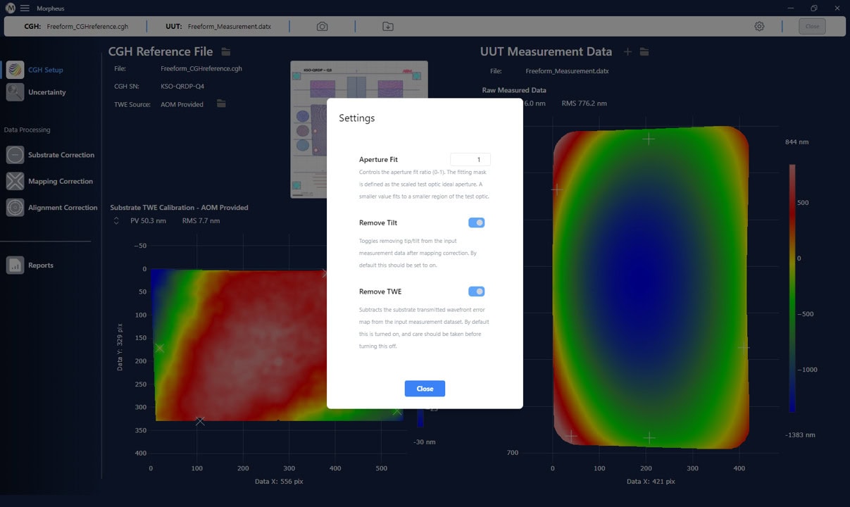
There are several important pieces of information now presented to you from the loaded UUT measurement data file:
- The aperture fit range is a number, which must be between 0 and 1, which defines the percent of the test optic aperture to utilize when fitting misalignment errors to the data output from mapping correction. To adjust, type a number in the box between 0 and 1. This then sets a mask, which is the ideal test optic aperture shape which the CGH was defined for, and scales its extent, centered on the center of the test optic aperture, by the input number. Thus, for a circular aperture optic for example, a value of 0 would mask all the data and fit nothing, a value of 0.5 would fit to a circle, on the results from mapping correction, whose radius is exactly 0.5 that of the full aperture, etc.
- The tilt is by default removed from the processed measurement data, after mapping correction. This is because any residual tilt is assumed to be a basic tilt that is present due to a misalignment between the test optic and the CGH. However, you can toggle to not remove tilt after this step, by pressing the toggle button.
- The transmitted wavefront error map for the CGH substrate is by default removed during substrate correction. This can be optionally not subtracted, but only in special cases. By not removing the substrate TWE there is the potential to introduce figure error which is not actually in the test optic surface into the final processed data. If you have any questions please contact AOM for more information.
- When you have adjusted the above according to your specifications, press the close button. This will rerun the processing of your data with the updated settings applied. If you have not adjusted any settings, closing this menu will simply close the settings panel without rerunning processing.
Next Steps
You are now ready to run the processing pipeline on your data. Please see the Processing the Data in Morpheus section of this manual for details on how to process your data in Morpheus™.