
Arc Focus Reference Alignment Patterns (AF)
| Name & IDs | Symbol | Typical Target Used | DOF and Sensitivity | Description |
|---|---|---|---|---|
| Arc Focus (AF-H, AF-V, AF-R, AF-T) | 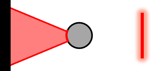 | Reflective Tooling Ball | Fine alignment of dX OR dY; (Pairs of patterns can also align dZ and clocking) | Projects a focused arc onto a curved reflective surface. Provides alignment in a single degree of freedom (along the line). AF-H, AF-V, AF-R, and AF-T specify Horizontal, Vertical, Radial, or Tangential |
How AFRs Work
Arc focus reference patterns create a line that comes to focus on the surface of a curved reflector, such as a spherical tooling ball. In one orientation, these rays form a catseye focus. In the other orientation, they make a confocal reflection.
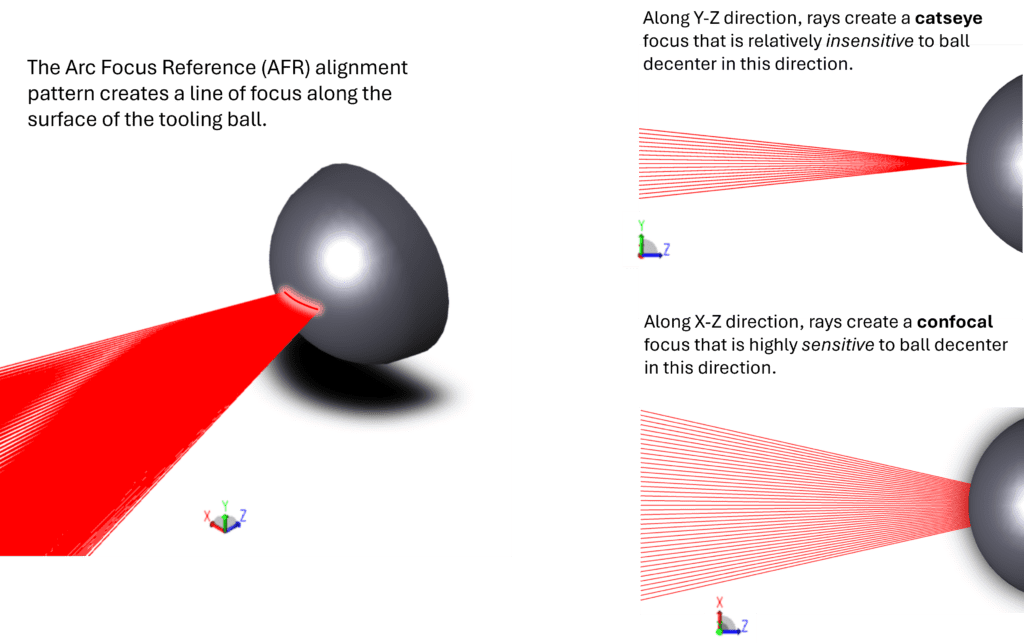
The arc focus pattern functions similarly to the Line Focus (LF) alignment pattern. In this case, the pattern is sensitive to motion along the direction of the line on the surface of the tooling ball, and is insensitive to motion across the line.
AOM adds a few fringes of tilt to this null state to aid in visual alignment of fringes; instead of obtaining a null interferogram, you instead make the “V” fringes parallel. The V fringes also help indicate the direction of misalignment.
A video illustrates dY alignment: Horizontal tilt fringes are reduced until only vertical tilt fringes remain. The objective is to make the remaining vertical tilt fringes parallel.
Click here for a summary table of all AOM alignment patterns.
When to Use AFRs: Close Working Distance Test Setups
AOM has recently developed Arc Focus Reference (AFR) patterns for alignment to tooling balls, a direct analog to the Line Focus Reference (LFR) pattern for Retroreflector targets. These patterns have equivalent alignment sensitivity at a given test geometry but offer additional benefits to setups with short working distances.
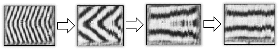
For test setups with a short working distance, using a pair of LFR patterns that are laterally separated on the CGH, targeting a single central SMR becomes problematic. SMRs have a limited “field of view”, such that at increased angles of incidence, rays get clipped, and fringe feedback of the alignment pattern is truncated. To adjust for this, an SMR can be rotated to point towards an alignment pattern, but this adjustment is limited when multiple patterns target a single SMR from different locations on the CGH.
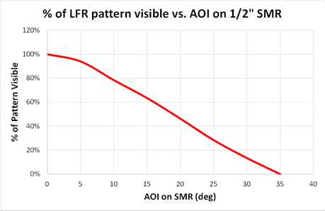
As an example, this plot shows the approximate fraction of an LFR pattern visible versus AOI for a ½” diameter SMR. Screenshots of the associated fringe patterns are shown below.
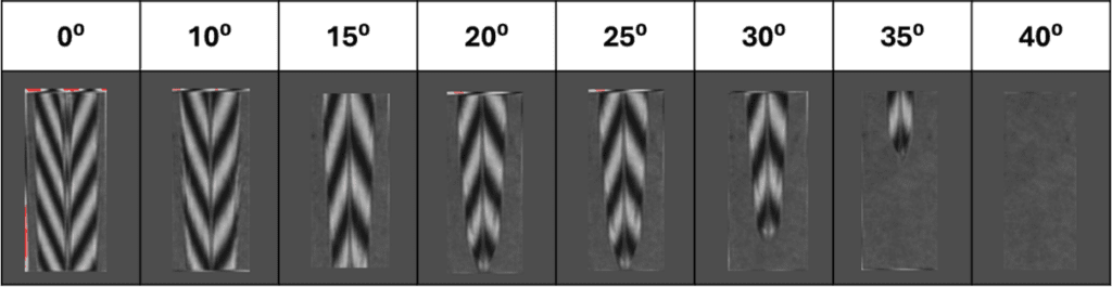
On the other hand, an AFR pattern creates a line focus along the surface of a sphere, and in doing so, there is no physical limitation created for angle of incidence of this line upon the sphere.
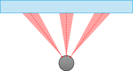
Top-down view of arc foci on tooling ball from various angles of incidence.
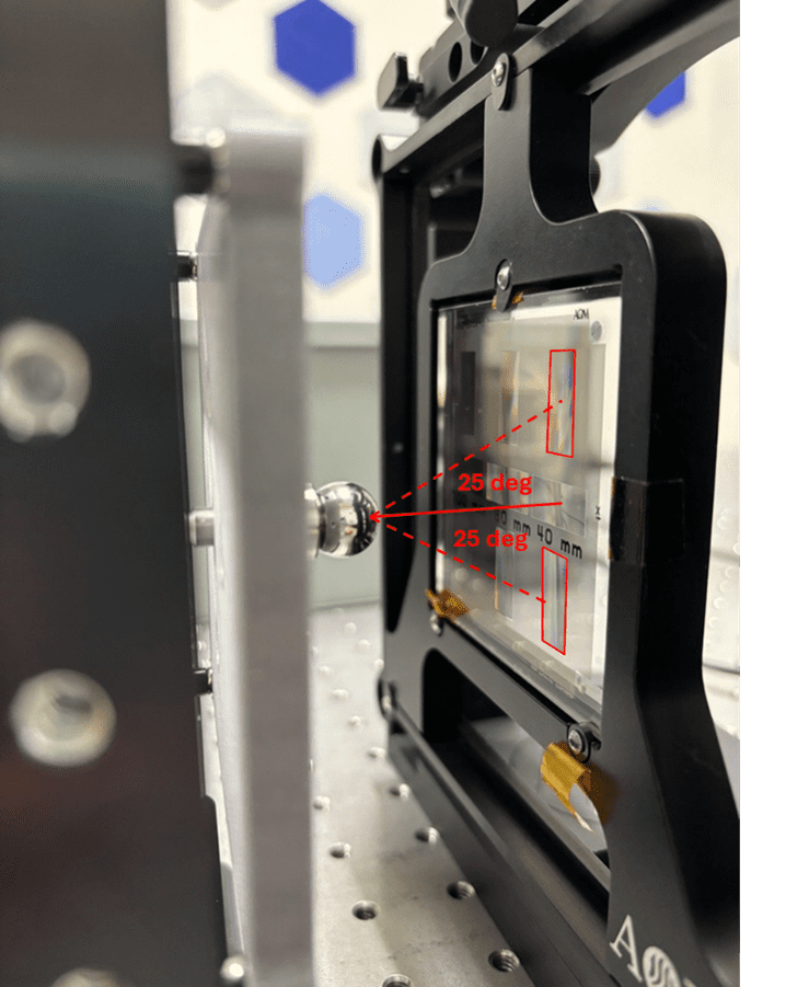
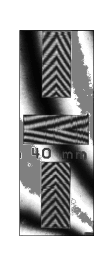
As an example, a pair of AFR patterns targeting a central ½” diameter tooling ball is shown below – the angle of incidence of these patterns on the ball is +/-25⁰. There is no clipping of the fringes in these patterns, as shown.
There are two requirements for successful use of the AFR pattern:
- Working distance should be relatively short to ensure sharp fringe patterns; the rule of thumb for a ½” tooling ball and typical pattern size is <200 mm working distance.
- Utilize a high-quality tooling ball with sufficient reflectance at the test wavelength. AOM recommends Grade 5 or Grade 10 balls and can give specific recommendations on ball material per the specific CGH test. AOM can also provide such tooling balls if requested.