How to Choose the Right Cylinder CGH
Read “How to Choose the Right Cylinder CGH” in Chinese.
Cylinder CGHs, or computer-generated holograms, allow for accurate characterization of cylindrical surfaces. While standard interferometer transmission optics are capable of easy and accurate characterization of surfaces, they are limited to the measurement of planar or spherical surfaces. Cylinder CGHs, on the other hand, create a cylindrical wavefront from a standard interferometer, and thus provide all the measurement benefits of interferometry for cylindrical surfaces. From a collimated input, a cylinder CGH creates a cylindrical wavefront with both converging and diverging wavefronts. A single cylinder hologram can measure a range of both concave (CC) and convex (CX) cylinder Units Under Test (UUTs).
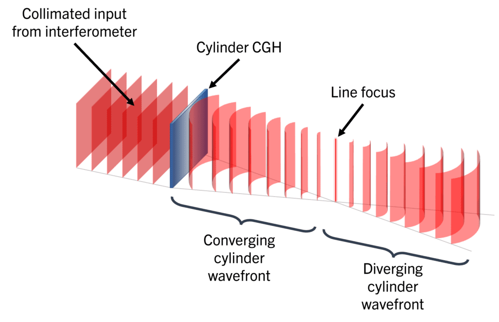
This article will walk you through the considerations required to select the proper cylinder CGH for your application. To simplify the selection process, we’ve created the Cylinder CGH Selection workbook available for download. Just input the parameters of your UUT and test setup and the calculator will highlight which of AOM’s cylinder holograms satisfy the geometric requirements, which we discuss below in depth.
The Cylinder UUT
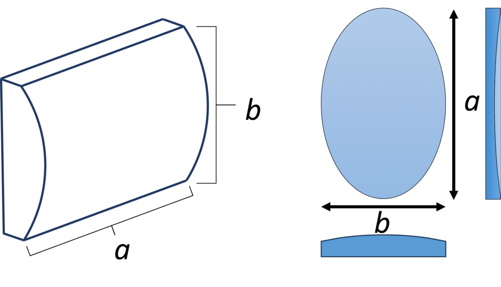
The geometry of the specific UUT is crucial to the selection of a cylinder hologram. We need to consider the radius of curvature (ROC), the surface shape (concave (CC) or convex (CX)), and the aperture shape and dimensions. For this article, the ROC is always positive and the shape of the surface is explicitly specified using CC or CX. In the case of a rectangular or elliptical aperture, the length of the UUT along the cylindrical axis (a) and the width along the curved direction (b) are important. In the case of a square or circle UUT, a = b. Throughout this article, we consider the cylinder’s r/#, which is the ratio of the ROC to the aperture and is given by

AOM Cylinder CGHs
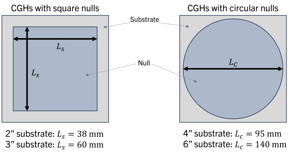
AOM offers cylinder computer-generated holograms in several substrate sizes and null pattern shapes for interferometers operating at 632.8 nm. Within the square substrate is a square or circular null pattern. This region creates the cylindrical wavefront. Square nulls are described by side length (Ls) while circular nulls are described by diameter (Lc). The accompanying diagram illustrates our available sizes for each shape.
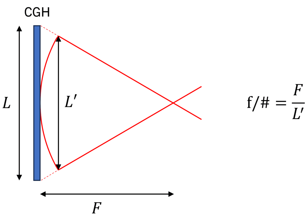
For each substrate size, we offer CGHs with various f/#s. The f/# is defined as the ratio between the focal length F and the effective aperture of the CGH and characterizes how rapidly the wavefront converges. Shown in the following figure, the effective aperture L’ is the width of the first unbroken cylindrical wavefront produced by the hologram. We use this definition for f/# because it is analog to cylinder’s r/# and makes selection of the CGH easier, as you’ll see below. For a comprehensive list of available AOM cylinder CGHs, visit our catalog of cylinder holograms.
Measurement of a Cylinder Surface
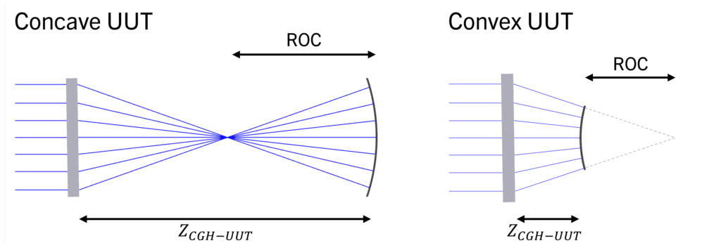
Typical setups for both concave (CC) and convex (CX) UUTs are shown below. AOM cylinder CGHs are designed for collimated input, so the spacing between the hologram and the interferometer is arbitrary. CC UUTs are measured in the diverging region while CX UUTs are measured in the converging region so that the wavefront of the hologram matches the shape of the cylinder surface. The UUT distance from the focus in each case is equal to the radius of curvature (ROC) of the UUT. This means that there is a specific measurement distance ZCGH-UUT. At this point, all rays are perpendicular to the UUT, which is set up for a null test.
How to Select a Cylinder CGH
In selecting a computer-generated hologram (CGH), we need to make sure that the cylindrical wavefront at the measurement location is large enough to cover the entire UUT, but still provides adequate resolution in the interferogram. In the case of convex (CX) UUTs, we also need to make sure the UUT will fit between the focus and the hologram. Lastly, the measurement geometry needs to be compatible with the setup and interferometer you have. The following discussion explains the geometric considerations to select the appropriate CGH. For your convenience, you can skip the math and download AOM’s Cylinder CGH Selection workbook which incorporates everything in the following discussion.
One of the benefits of cylinder CGHs is that a single hologram can measure a range of UUTs. You may want to consider current and future applications when selecting a CGH. If you need metrology for more than one cylinder surface, it may be possible to find a single hologram that works across all applications.
1. Determine the maximum f/#
The f/# of the CGH determines the coverage of the wavefront on the curved dimension of your UUT. To ensure complete filling of the UUT, the f/# must be less than or equal to the r/# of your cylinder:

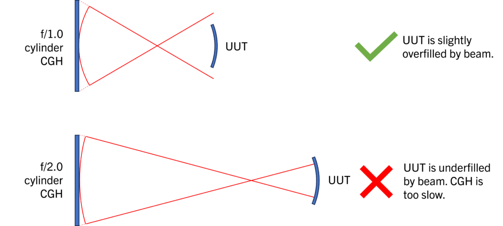
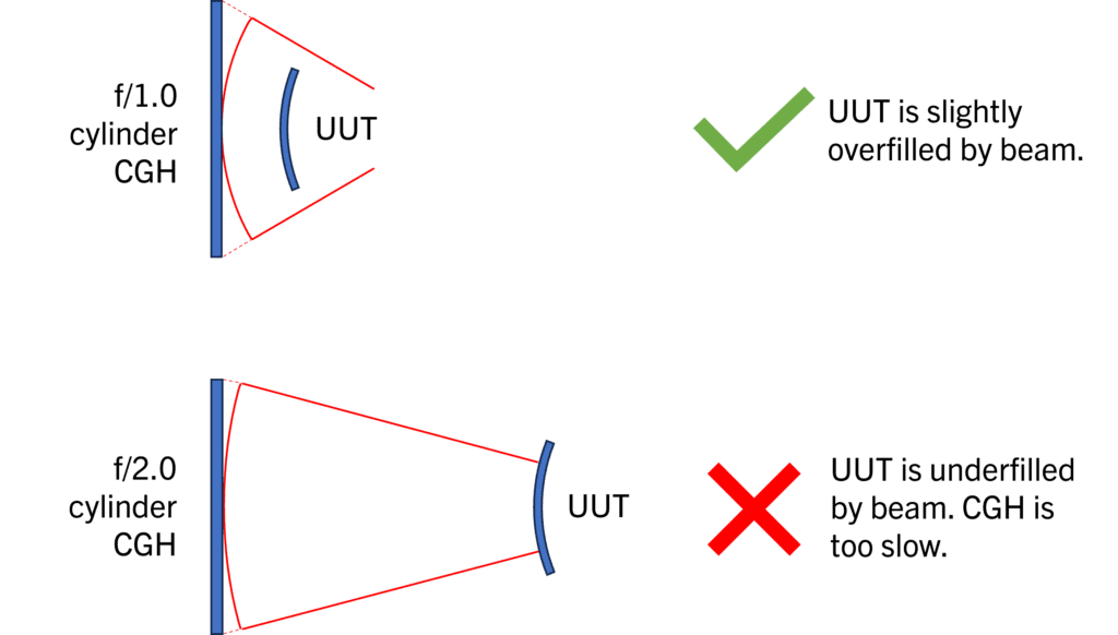
The effect of f/# on filling is illustrated below for both CC (concave) and CX (convex) UUTs. For each UUT, the first case shows a correct selection of a cylinder CGH, where the wavefront fills or slightly overfills the r/1.4 cylinder UUT. The second diagram shows underfilling when the f/# is too high. In this case, the entire UUT cannot be measured.
Effect of f/# on filling of a r/1.4 CC cylinder:
Effect of f/# on filling of a r/1.4 CX cylinder:
2. Select the f/# for appropriate filling
While satisfying the above condition means the curved direction of the UUT will fit within the CGH, it’s preferable that the UUT isn’t excessively overfilled to maximize the resolution of your data. The following discussion of the geometry of CGH filling gets somewhat technical and is included for the interested reader. As a reminder, all the mathematical considerations are embedded in AOM’s Cylinder CGH Selection workbook so you can be sure you’re selecting the appropriate hologram without performing the calculations.
When measuring cylinders, the image on the interferogram is the projection of the UUT’s wavefront on the CGH. This projection distorts the scale along the curved direction, an effect called mapping distortion, which can be seen in the diagram below. The projection of the UUT’s curved direction onto the CGH is depicted by the solid lines. The dashed lines show the projection of the CGH wavefront onto the UUT. Because the condition above is satisfied (f/# < r/#), the UUT is entirely filled.
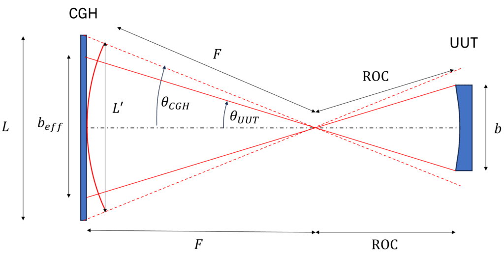
To maximize the resolution of the image, we want to make sure that the projected width of the part onto the CGH beff is as large as possible while still fitting onto the hologram. To do this, we can introduce a filling factor s defined as the ratio between the width of the hologram L and beff. Using the diagram, we find:
From the diagram, we can evaluate the trigonometric functions in terms of the CGH f/# and the cylinder r/#:

Similarly,
Together, then, the filling factor is

The figures below show how s affects the UUT footprint along the curved dimension (beff) in the interferogram. AOM recommends 1 ≤ s ≤ 2 for an optimal measurement. It is also reasonable to measure with 2 < s ≤ 4, however, the footprint of the UUT on the hologram will be narrow and therefore have a lower resolution on the interferogram along the curved direction. You can technically take a measurement with s > 4, and this might be acceptable if you don’t need high-resolution data or if you have an interferometer with higher than standard resolution, but it is generally not recommended.
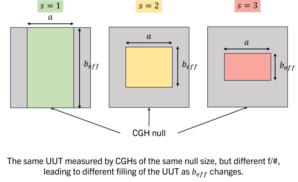
Depending on your application, you may need your data in real space coordinates, which requires undistorting the footprint on the CGH. AOM’s CGH data processing software Morpheus™ is designed to do that (and so much more) and is compatible with all our cylinder computer-generated holograms!
3. Verify a CX UUT will fit
When selecting a CGH f/# for CX UUTs, an additional requirement must be met to ensure that the UUT can be placed between the CGH and the focus. Based on your test setup and preferences, determine the minimum spacing you’ll want between the hologram and UUT. We’ll call this distance d. AOM recommends d = 5 mm. The condition to satisfy is F ≥ ROC + d.
4. Select the CGH size
The f/# selection ensures that the dimension along the curved direction will be filled, but we also require that the wavefront fills the axial direction of the UUT. This is accomplished by selecting the size and shape of the hologram.
- For rectangular or square UUTs:
- For square CGHs: a ≤ Ls
- For circular CGHs, we must consider the diagonal of the projected rectangular UUT fits into the circular CGH null. In this case, we need to satisfy a2 + beff2 ≤ LC2. From the setup diagram, we find
 After substitution, the condition becomes

- For circular or elliptical UUTs, a ≤ L (for both square and circular CGHs).
One other consideration for size is the interferometer available to you. A 4-inch interferometer is compatible with 2, 3, and 4-inch CGHs, while a 6-inch interferometer is compatible with cylinder CGHs up to 6 inches.
If measurement space is limited, you should also verify that the measurement distance between the hologram and UUT will fit in your available space. CGH-UUT spacings ZCGH-UUT are:
- For CC UUTs: ZCGH-UUT = F + ROC
- For CX UUTs: ZCGH-UUT = F – ROC
Ready to order or need more assistance?
- 2-inch cylinder CGHs and compatible stages are available and ready to ship from Edmund Optics!
- 3-inch cylinder CGHs are available and ready to ship from AOM. If you prefer the 3-inch CGH mounted in a 6-inch cell, you can inquire about a custom order.
- 4 and 6-inch CGHs are available by custom order.
- We can also custom-design cylinder CGHs for test wavelengths other than 633 nm.
Contact AOM for assistance in selecting a cylinder CGH or designing your metrology system today!