
Argus Method for Telescope Alignment
An Introduction to Fast and Accurate Telescope Alignment Using CGHs
Two-mirror telescope systems have been manufactured and assembled for many years to support high-precision imaging, free-space communications, and high-energy laser applications, among others. Deployment of such systems is growing from one-off specialized units into production volumes in the 10s or 100s as the demand increases for rapid refresh earth imaging, faster and further reach of data, and defense of airborne threats and ballistic missiles.
Broad deployment of these kinds of optical systems at volume drives the need for efficiency in fabrication, while precision and accuracy requirements continue to tighten. Traditional methods of system alignment are difficult, tedious, or simply intractable for production. Often, the capabilities for such precision fabrication and alignment are closely guarded trade secrets within the institutions that develop them.
AOM has developed the Argus Alignment™ Method to support the growth in precision optical systems fabrication. This holistic approach to subsystem alignment provides complete knowledge of element alignment and subsystem alignment to back-end optical subsystems.
Standard Alignment Methods
A typical Cassegrain telescope is assembled with a concave conic primary mirror (PM) and a smaller aspheric convex secondary mirror (SM). The telescope’s performance hinges largely on the precise alignment of these two mirrors. The PM/SM pair often have significant field aberrations that require correction optics to remove these errors in final operation. Aligning the telescope can be time-consuming as reducing both on- and off-axis aberrations is required. This involves iterative processes and can require specialized equipment such as laser trackers or coordinate measuring machines to set up a wavefront test at each field point.
Testing field points traditionally requires positioning the interferometer to various field points, adjustment of the corrector optics, as well as scanning of field angles using an auto-collimating flat (ACF). These methods drive complexity, and potentially cost, of aligning a system of several optical elements. A brief description of traditional alignment methods and their limitations is shown below for illustration.
Off-axis or Field-Point Alignment
Testing for field performance is often the most labor-intensive process of a PM/SM alignment process. Field testing requires precise knowledge of coordinate systems between datums and components to reasonably iterate into the performance spec of the system. If after making an adjustment to the system alignment, the field tests indicate an error greater than the performance specification, another iteration of alignment is often needed. This can be slow and cumbersome.
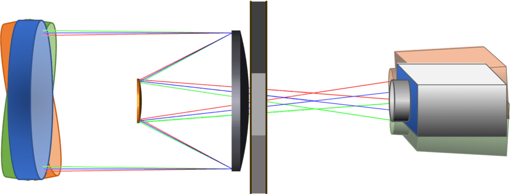
PM/SM subassembly in a traditional field point test with interferometer positioned at multiple field points, and auto-collimating flat (ACF) tilted to return field angles.

Traditional alignment process for PM/SM telescope subassembly.
Argus Alignment™: The Holistic Solution
The Argus Alignment method from AOM offers a simpler and more accurate method for aligning a PM/SM subsystem using computer-generated holograms (CGHs). Appropriately named after Argus Panoptes, the mythological Greek figure that was all-seeing with 100 eyes, the AOM solution provides feedback for all degrees of freedom (DOFs) simultaneously at each step of the alignment process – no iteration required.
Utilizing two holograms, each with multiple patterns that are imaged in an interferometer simultaneously, two static test setups enable alignment of all DOFs of a PM and SM mirror subsystem.
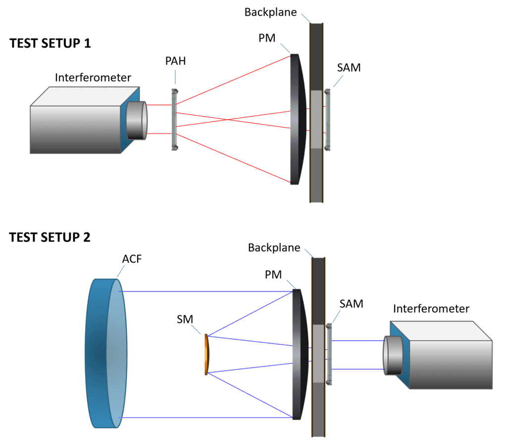
Argus Alignment method test setup 1 – PM alignment to the strongback setting the system optical axis (top). Argus Alignment method test setup 2 – SM alignment to the PM and system optical axis (bottom).
The key elements of the test are the Primary Alignment Hologram (PAH) and a System Alignment Master (SAM), CGHs with patterns specific to the subsystem wavefronts and required alignment element. Simple hardware for positioning and aligning the PAH and SAM are also required.
Both elements, the PM and SM, commonly have 5 DOFs each. The Argus method simplifies the process of aligning the two elements by using multiple holographic patterns to decouple DOFs and provide simultaneous feedback for each. For instance, in a typical field-point alignment strategy, tilt and decenter are coupled such that it is ambiguous which to adjust using on-axis wavefront feedback. When tilt is corrected by decenter on-axis, or vice versa, field performance suffers. But the Argus method separates these DOFs for explicit alignment of each for both elements in the on-axis test setups. Once the two Argus test setups are completed, field performance can optionally be verified using the SAM CGH, again without the need to reposition the interferometer for each field point.
How It Works
Leveraging Flexibility of CGHs
The Argus Alignment method utilizes CGHs, which are precision diffractive optical elements. They are produced by lithographic processes that print specified diffractive patterns on an optical window, usually 6” x 6” x ¼” thick. This process also enables any number of patterns in any desired configuration to be printed on a substrate, with co-registration of the patterns maintained to nanometer precision in lateral positioning and sub-arcsecond in angle space.
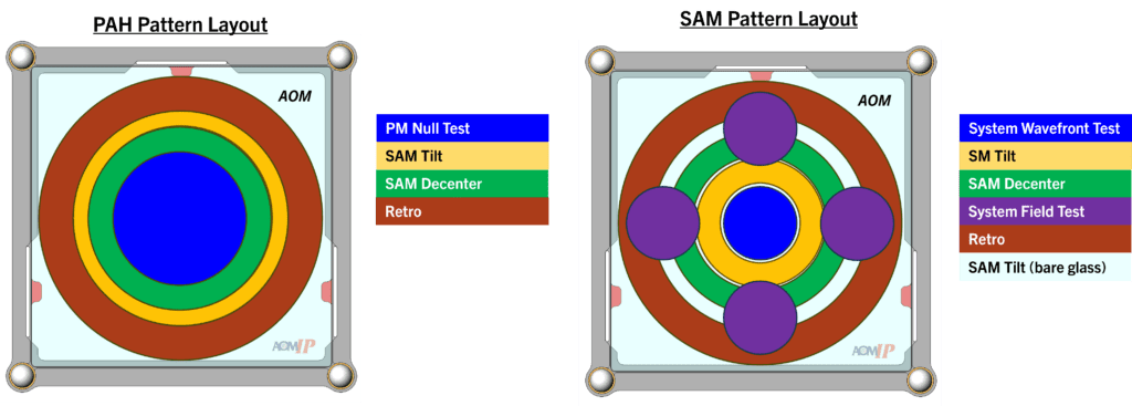
Both the PAH and SAM CGHs include a set of zones that provide fringe feedback for aligning a particular aspect of the subsystem. These zones are labeled in the accompanying diagrams and their specific uses will be described in the procedure in the next section. Note that in practice, the positions of the zones on the CGHs may change due to the telescope geometry, but the functionality remains the same.
The Alignment Process
The Argus Alignment procedure is simple and has three sequential phases:
- The mounting plate and SAM are mounted to the backplane of the telescope.
- The PAH facilitates the alignment of the PM to the SAM.
- The SM is aligned using the SAM in conjunction with an ACF.
These steps are described in more detail in the following sections. Note: the steps outlined in this document represent the preferred AOM approach to this alignment method, however, the test can be configured to conform to individualized system requirements and restrictions on adjustability.
Mounting the SAM
The SAM mounting plate is designed to securely attach to the telescope’s backplane using existing features, ideally the interface features that will later mount aft corrector optics. Given that the interface features can be accurately measured using a CMM, this allows the features to define a Master Coordinate System (MCS) and can be used as references for mounting other features or aligning additional subsystems. This arrangement enables precise alignment of the telescope optical axis with respect to the MCS. Because the SAM mounting plate can make use of existing features, it is important to consider alignment and metrology during the design phase. Commonly, the MCS is defined by three pads that establish a plane and two pins that define an origin and control clocking.

Telescope backplane structure example (left). Mounting mechanics for aft optics assembly, also used to mount SAM adapter plate (right).
Once the SAM mounting plate is installed, the hologram can easily be mounted to the plate using AOM’s magnetic kinematic cone-vee-flat mounting features.
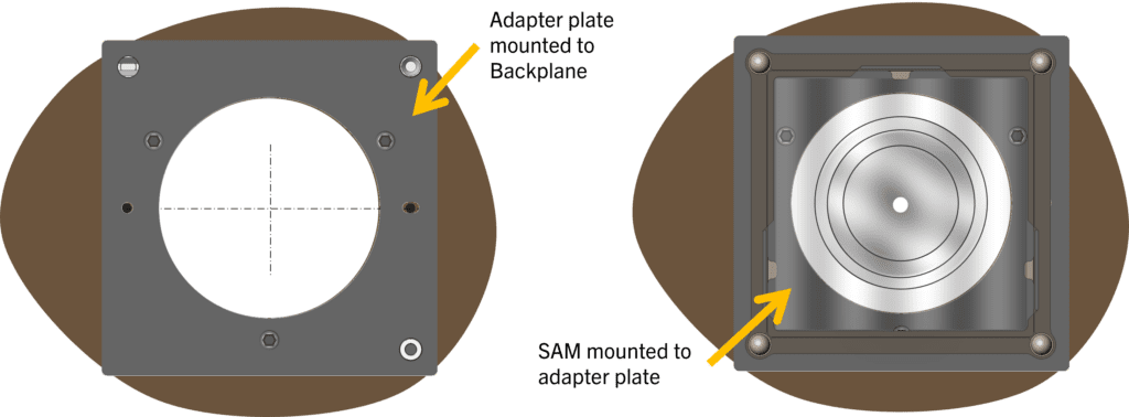
SAM adapter plate mounted to telescope backplane (left). SAM mounted to adapter plate (right).
Aligning the PM to the Backplate Using the PAH
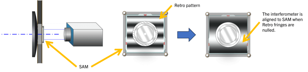
The PAH aligns the PM relative to the SAM, and thus the telescope backplane. First, the PAH is mounted in a 6 DOF stage and aligned to the interferometer. The outer zone of the PAH serves as a Retro pattern, which is designed for alignment feedback to the interferometer. For collimated interferometer beams, this pattern will produce fringe feedback to align tilt, and for spherical interferometer beams, it will produce feedback to align tilt and Z. In both cases, the PAH is aligned to the interferometer when the Retro pattern is nulled.
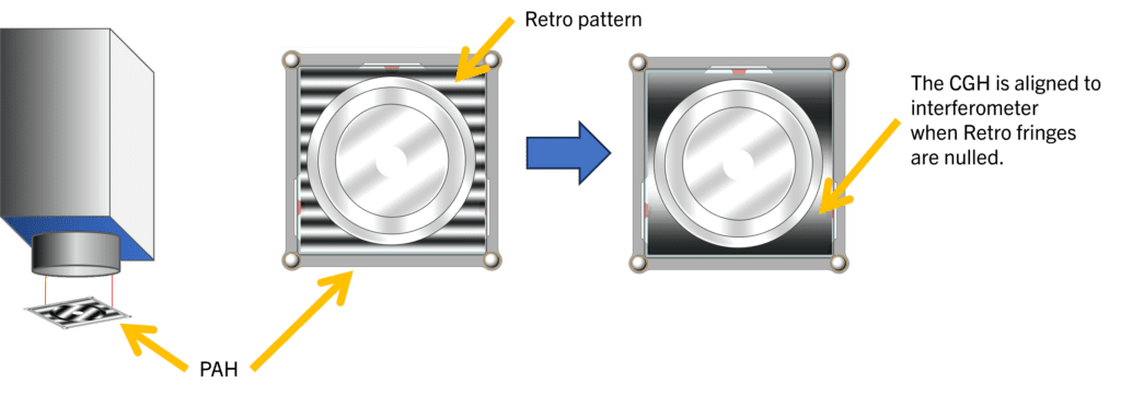
PAH CGH and its alignment to interferometer – the PAH can be designed for either a collimated or a spherical input beam.
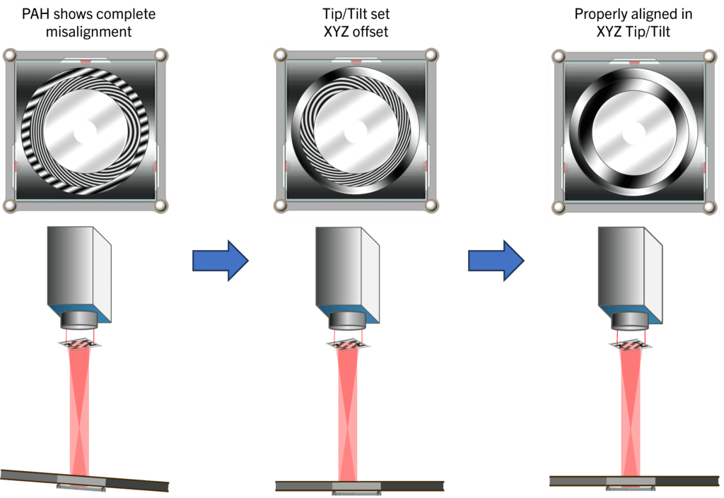
Next, the SAM, already mounted to the backplane, needs to be aligned to the PAH. The PAH has two zones to facilitate this alignment. On the PAH, the Tilt zone produces a collimated beam which is reflected off the corresponding pattern on the SAM, serving as the tilt reference between the two. The Decenter zone of the PAH creates a spherical wavefront that reflects off the Decenter zone of the SAM, providing feedback for X, Y, and Z alignment between the two.
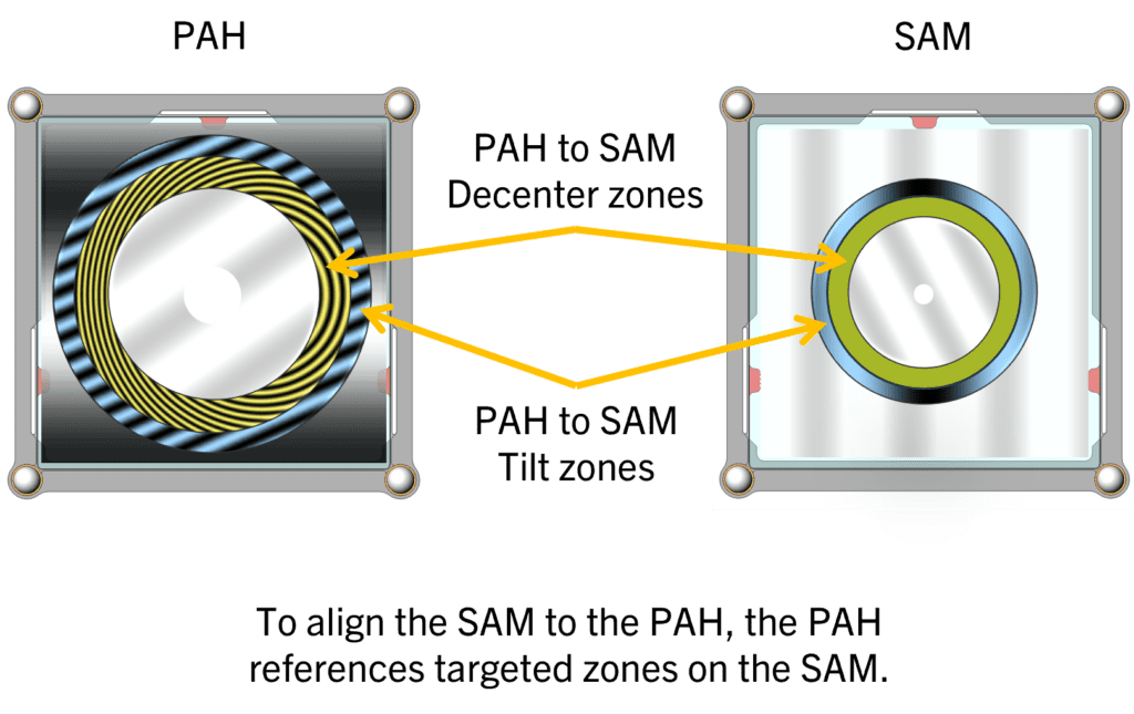
These two zones are used together to adjust all five degrees of freedom (X, Y, Z, and tilt) of the backplane unit. Once both regions are nulled, the backplane is aligned.
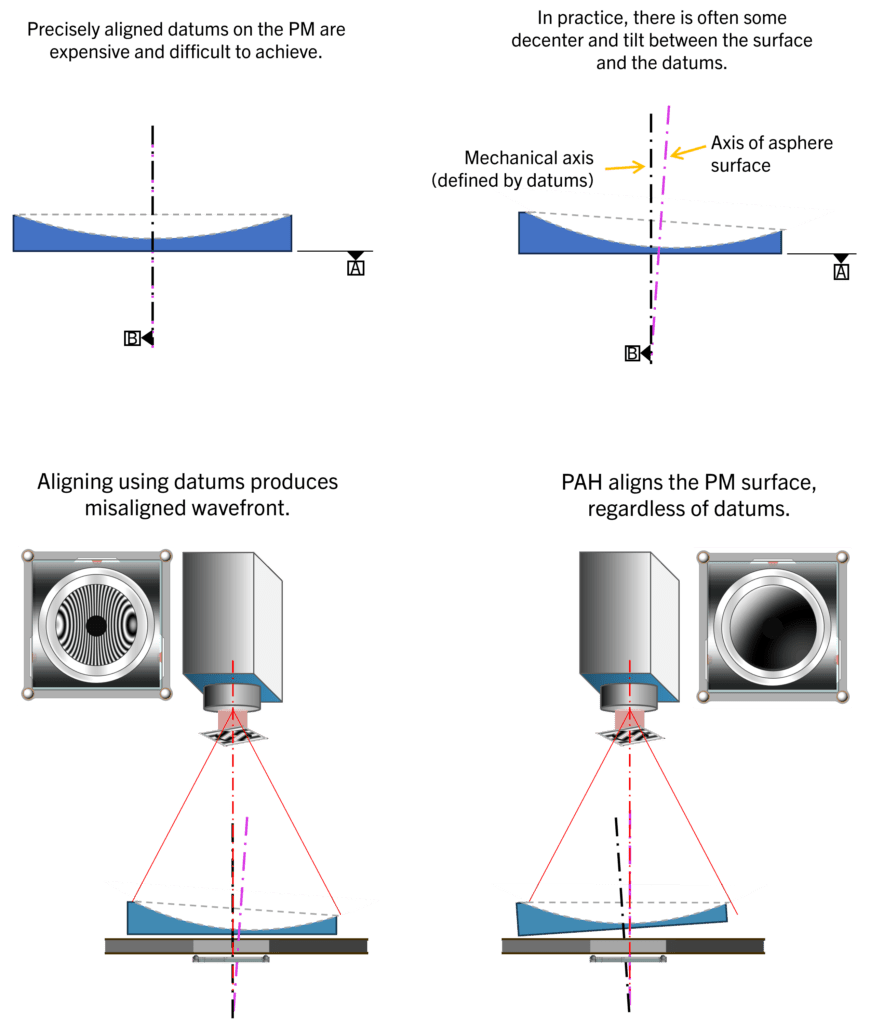
Now, the PM can be installed and accurately aligned relative to the SAM/backplane unit using the PM Null Test zone. Five degrees of freedom are controlled through the PM Null Test zone in the PAH – tilt in the interferogram is tilt in the PM, power feeds back spacing error, and coma provides decenter feedback. This is the same concept as a surface test, and in fact, the PAH can also be used to verify the surface figure error of the PM.
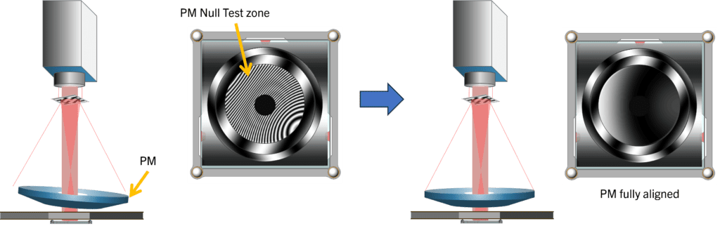
It is worth noting, with this method only the optical surface is used for feedback and alignment to the backplane, there is no reliance on precision to mechanical datums of the PM. This allows for relaxed mechanical tolerances during PM specification and fabrication, which in turn reduces effort and cost.
An alternate alignment method to the AOM-preferred MCS approach can be applied where the PM is first fixed to the backplate and then the PAH is aligned to the PM before continuing with the alignment process for the SAM. This approach requires careful control and transfer of the PM datums throughout the setup as shown in the example above.
Aligning the SM to the PM Using the SAM
At this stage, the PM and backplane/SAM assembly are well aligned. The interferometer is moved to the 2nd test configuration such that it is on the opposite side of the SAM. The interferometer is aligned to the SAM using its Retro pattern. Like the PAH, the Retro pattern is designed to provide alignment feedback for either collimated or spherical input wavefront.
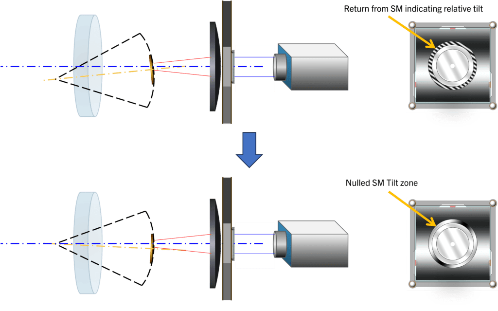
Next is the alignment of the SM. There are two patterns on the SAM to aid with this step, the SM Tilt zone and System Wavefront Test zone. The SM Tilt zone is used for tilt feedback of the SM. When nulled, the center of curvature of the SM lies along the optical axis, however, the mirror itself may be decentered from the optical axis and PM-SM spacing may not yet be correct. These DOFs are corrected in the next step.
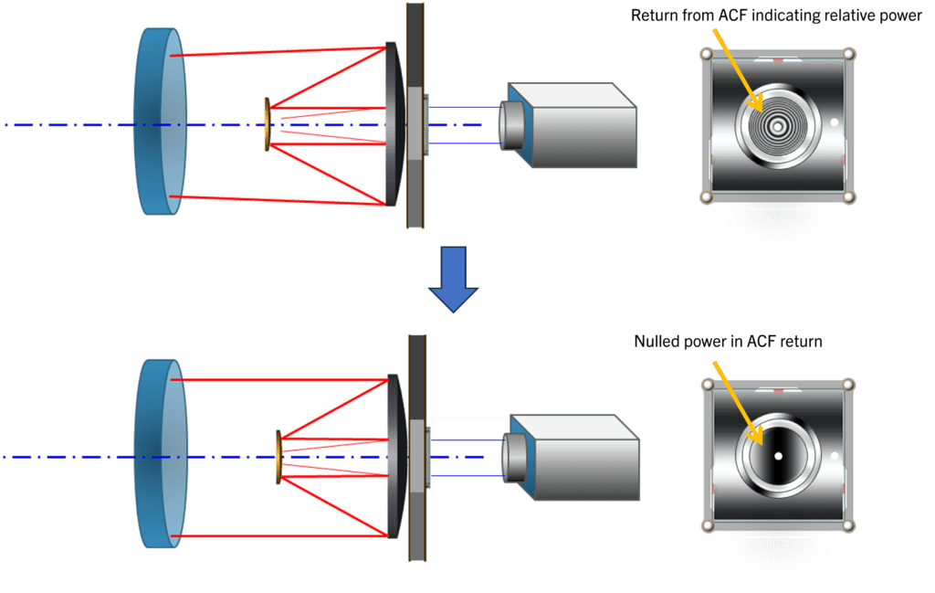
SM centration and spacing error remain after tilt is corrected and are aligned using the System Wavefront Test zone on the SAM. Coma, combined with power, are the dominant aberrations in the System Wavefront Test zone in this state and are the aberrations used for feedback of the SM axial spacing and decenter. Power is minimized by adjusting axial position of the SM while coma is minimized by adjusting SM decenter. Once only tilt fringes remain in the System Wavefront Test zone, the ACF can be adjusted to remove them.
Field-Point Verification
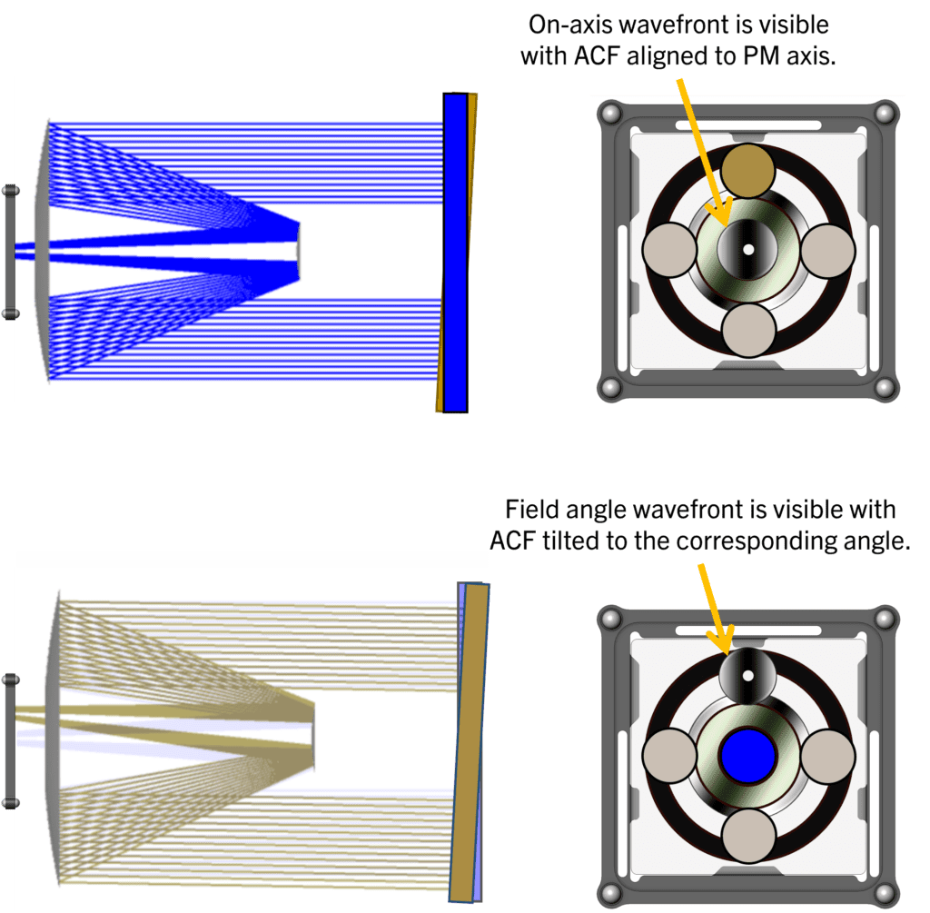
The SAM can be designed to illuminate the system with ideal wavefronts from multiple field points by adding extra patterns to project test wavefronts through the system at the desired field angle(s). While maintaining the interferometer on-axis, each field point can be tested by tilting the ACF to the corresponding angle without moving any other equipment or hardware. Since this test is done in the same configuration as the SM alignment, it can be done before permanently fixing the SM in the system.
A key advantage of the Argus Alignment method is the ability to sense and measure linear field-dependent astigmatism (LFDA). Tilt misalignment between the PM and SM causes a shift in the nominal field point and its associated field angle, creating the source of this field aberration. AOM provides an estimate of this field aberration along with on-axis coma and astigmatism based on the uncertainty in SAM position and residual misalignment of the test. When required, accuracy of the LFDA measurement can be improved by fitting the astigmatism at all field points and making a deterministic correction based on the measured data. Performing this process iteratively can reduce the error estimated in the AOM error budget.
Conclusion
AOM’s Argus Alignment method is a novel and comprehensive approach to telescope alignment, enabled by the flexibility and precision of CGHs and rigorous test design – each of which are core competencies of AOM. It significantly mitigates risk of telescope assembly, integration, and test with early and careful planning and enables high precision and reliable alignment tailored for production volumes of telescope systems.
AOM collaborates closely with customers to design customized alignment and metrology strategies and provides guidance throughout the design and implementation process. Contact AOM today to learn how your next telescope production project can benefit from the Argus Alignment method.