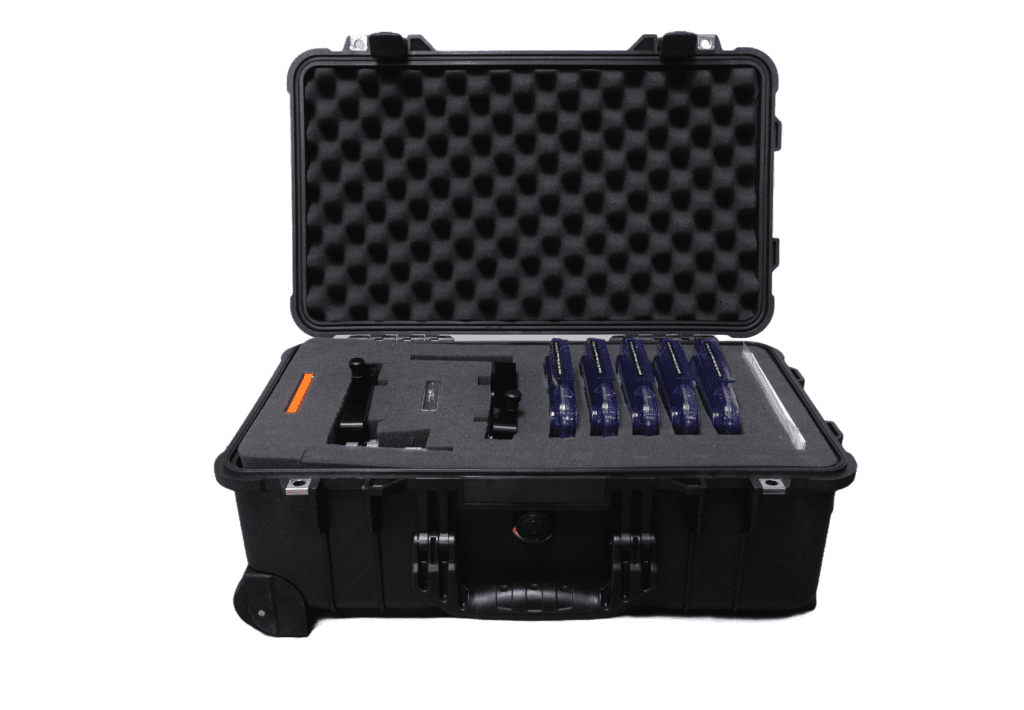
3-Inch Cylinder CGH Kit
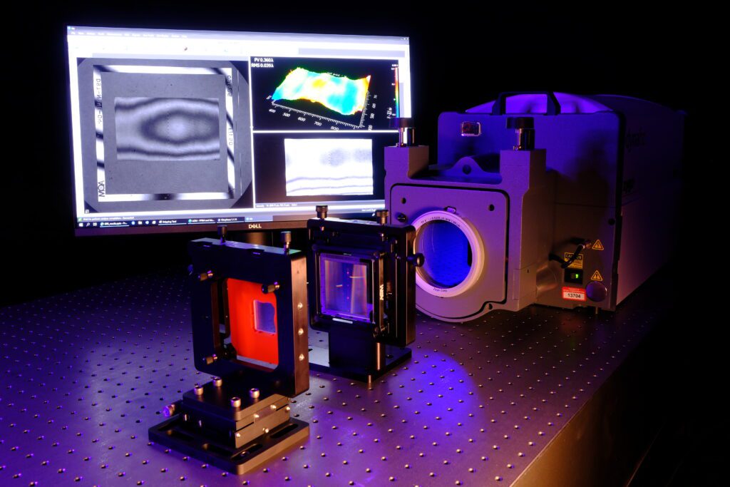
AOM’s 3-Inch Cylinder CGH Kit is a curated set of hardware to enable you to quickly start measuring cylinder surfaces using a standard Fizeau interferometer and transmission flat. Multiple cylinder CGHs (computer-generated holograms) are included to ensure an optimal measurement for a wide range of cylinder surfaces. Two fine alignment stages facilitate mounting and alignment of the CGH and test part. Get started by measuring our included sample cylinder lens or jump right in with your own cylinder surfaces!
Kit Contents
- 5x 3-inch Cylinder CGHs with the following f/#
- f/0.7 (C3070S)
- f/1.0 (C3100S)
- f/1.5 (C3150S)
- f/3.0 (C3300S)
- f/6.0 (C3600S)
- Fine alignment stage with linear positioner (FP3-Z-H425)
- Fine alignment stage (FP3-H425)
- Sample cylinder lens (THORLabs LK1743L1)
- 3D printed test part fixture & digital file to print your own
- 20x ¼” magnetic mounting balls (for attachment to your own 3D printed fixtures)
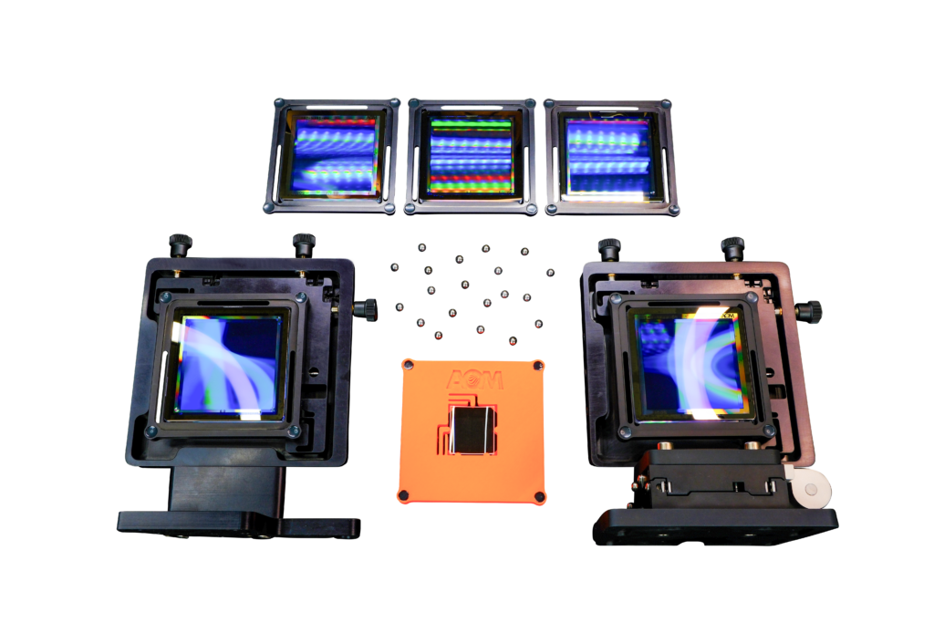
CGH Specs
| Model | f/# | Distance to Focus (mm) |
|---|---|---|
| C3070S | 0.7 | 29.4 |
| C3100S | 1.0 | 52.0 |
| C3150S | 1.5 | 84.9 |
| C3300S | 3.0 | 177.5 |
| C3600S | 6.0 | 358.7 |
For all 3-inch cylinder CGHs:
| Null pattern size | 38 mm |
| Retro pattern size | 67.2 mm |
| Input beam | Collimated (TF) |
| Operating wavelength | 632.8 |
| Grating type | Binary phase |
| CGH tilt wrt interferometer | -1° about X (+Y toward intf.) |
| Test optic tilt wrt CGH | 1° about Y (+X toward intf.) |
For more detailed dimensional and interface information, see customer drawings C3XXXS.PDF and C3XXXS.STEP.
Download the 3-Inch Cylinder CGH Datasheet (also available in Chinese – 3英寸柱面CGH).
After mounting the hologram to the stage using the magnetic interface, place it with the patterned side facing away from the interferometer. Align it using the proper tilt indicated above. Use the fine positioners of the stage to null the retro zone.
Test Part Fixture
Mounting and alignment of a test optic to the CGH is critical but also needs to be flexible to adapt to your specific test part form factor. We make this easy by providing a CAD model blank for a fixture that can mount directly to the AOM FP3 alignment stage. Download the CAD model, design the part-specific interface features, and 3D print or machine out of aluminum.
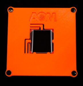
The design is ready to be printed for use with the included sample UUT or you can customize it to fit your own part. Magnetic mounting balls are included in the kit that interface to the FP3 stage. Once the mount is printed, bond the included ¼” balls into the pockets in all 4 corners on the backside of the mount (the side without the AOM logo). We recommend 3M DP420 epoxy.
Test Geometry
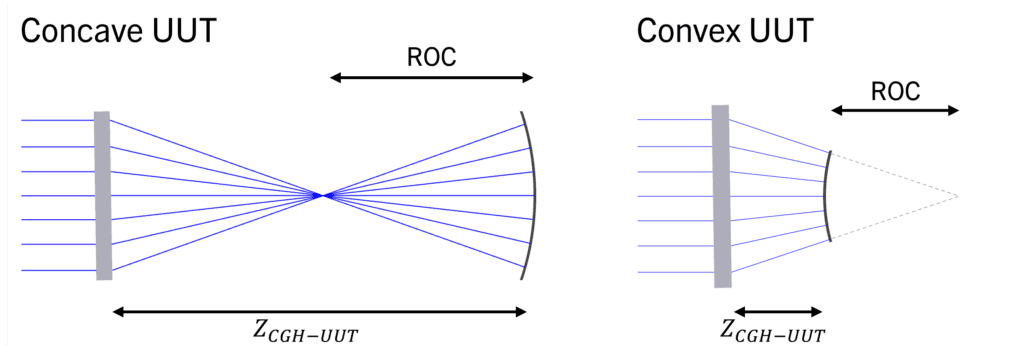
Measuring a cylinder optic with a CGH is similar to measuring a spherical optic with a transmission sphere. A spherical optic surface can be measured by placing it at the confocal spherical wavefront produced by a transmission sphere. A cylinder measurement is similar, except that the CGH creates a cylindrical wavefront instead of spherical, and the cylinder is placed at the confocal cylindrical wavefront.
To measure a cylinder UUT, place the surface at the location confocal with the CGH.
Selecting the Right CGH for your UUT
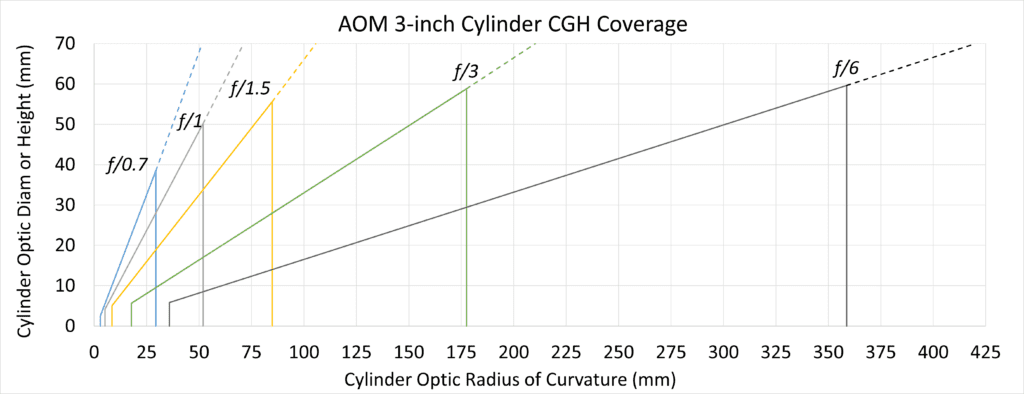
- Any convex UUT that falls below the solid line corresponding to any given CGH can be measured by that CGH.
- Any concave UUT that falls below the solid or dashed line corresponding to any given CGH can be measured by that CGH.
- For the best resolution, select the largest f/# CGH that is capable of measuring your UUT.
For a more in-depth understanding of selecting a cylinder CGH, read our tech memo, How to Choose the Right Cylinder CGH (also available in Chinese), or download the AOM Cylinder CGH Selector Workbook to calculate UUT coverage and CGH-UUT spacing. You can also visit our Guide to Cylinder CGHs for all of our resources relating to cylinder CGHs.
Purchase a Kit Today
The AOM Cylinder CGH Kit is an all-in-one package that enables you to achieve precision measurements for a range of cylinder optics. Reach out to get your kit today!
