
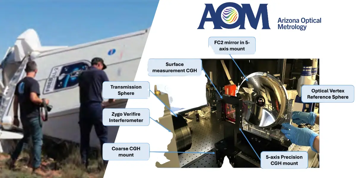
CASE STUDY // CUSTOM CGH ALIGNMENT // FIREBALL-2
AT A GLANCE
Customer: University of Arizona & the NASA/CNES FIREBall-2 collaboration, led by Dr. Simran Agarwal and Dr. Aafaque Khan
Challenge: Realign a damaged two-mirror corrector to ±25 µm and 1 arcminute, without touching the UV coatings, with a four-month deadline
Solution: Two custom CGH nulls on a single substrate: one to verify the damaged mirror’s surface, one to align both mirrors
Outcome: Alignment within tolerance, image quality better than the original build, and a successful flight in September 2023
01 — THE MISSION
A Telescope Suspended from a Balloon
FIREBall-2 is a NASA/CNES astronomy experiment with an unusual observing platform. Its 1-meter telescope and ultraviolet, multi-object spectrograph are suspended beneath a stratospheric balloon, floating high enough to see UV light that never reaches the ground.
The instruments’ science target is the circumgalactic medium, the faint halo of gas that surrounds galaxies and feeds their star formation. That gas glows near 205 nm, a wavelength that the atmosphere absorbs almost completely. It is, however, readily detectable at balloon altitudes.
The FIREBall-2 observatory was designed to trace this diffuse gas, helping astronomers to understand its role in galactic formation. The unique payload was built and flown by a collaboration led by the University of Arizona and Caltech.
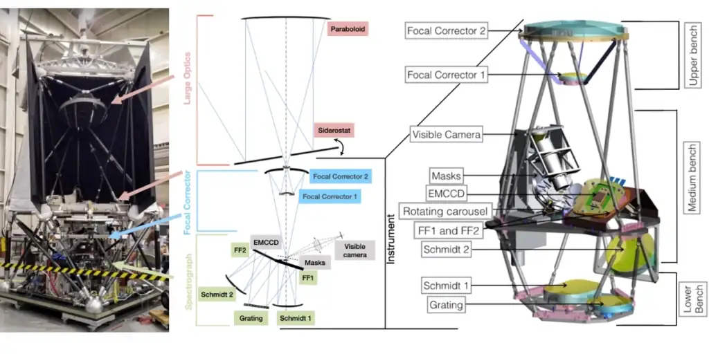
Fig. 1 — The FIREBall-2 payload: gondola (left), optical path (center), and the instrument stack (right). The two focal corrector mirrors, FC1 and FC2, sit at the top of the spectrograph assembly. Image: Agarwal et al., JATIS (2025).
02 — THE PROBLEM
A Hard Landing
On its first flight in September 2018, FIREBall-2 launched cleanly from Fort Sumner, New Mexico. Then, a puncture in the balloon forced an early termination of the flight. The gondola landed harder than planned. When the recovery team reached it, the structure and telescope mirrors showed clear signs of impact. One optic in particular: FC2, the larger of the two mirrors in the telescope’s focal corrector, had fractured at one of its bond pads (Figure 2). A piece of the substrate, pad and all, had broken off.
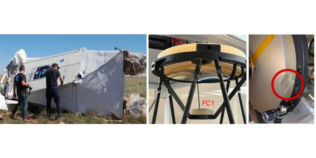
Fig. 2 — Left: the recovery team reaches the gondola the night after the 2018 flight. Center: the focal corrector assembly before flight. Right: the fracture at one of FC2 bond pads (circled). Image: Agarwal et al., JATIS (2025).
The focal corrector is a critical, precision optical assembly. It consists of a small convex hyperboloid (FC1) facing a large concave ellipsoid (FC2). Together, the two mirrors re-image the telescope’s focal plane onto the spectrograph’s slit mask, correcting coma across a wide field of view while holding the magnification almost exactly at one. Achieving this correction requires the two mirrors to be aligned within 25 microns laterally, with spacing controlled to 40 microns and relative tilt under one arcminute. If these tolerances are not met, the galaxy targets will not align with the slit mask, and the spectrograph cannot perform its analysis.
03 — THE CONSTRAINTS
Why the Original Alignment Method Wouldn’t Work
The focal corrector had been aligned once before, for the first flight. At that time, the team was able to use a traditional alignment approach: a 5-micron pinhole source, a microscope camera, a crosshair fixture seated in FC2’s central hole, and a CMM (coordinate measuring machine) arm to iterate positions. The team inferred alignment from the quality of an on-axis image spot, then cross-checked it using contact metrology. Careful characterization was needed at every stage to keep tolerances from stacking up. The alignment was successful, but it was slow and indirect.
Following the damage to the corrector, a repair attempt was made during the Covid pandemic to prepare the observatory for a planned 2022 flight. The attempt exposed the difficulty of using this method under pressure. When that flight was canceled, the team decided to fully debond the optics and realign the corrector properly for a Fall 2023 campaign. The deadline was still daunting: all test design, fabrication, alignment, bonding, and verification had to be completed in roughly four months.
In addition to the tight timeline, a second constraint made re-alignment even more challenging. The mirrors’ UV-optimized coatings are highly sensitive to contamination, and any contact with the mirrors risked depositing material on the optical surfaces. Contact-based metrology would not be an option; only non-contact methods would be possible
The team needed a way to measure mirror positions directly, in real units, in real time, without touching either mirror surface. It was at this point when the project turned to Arizona Optical Metrology for this mission-critical solution.
04 — A SHORT PRIMER
How a CGH Works
Precision optics are typically tested using non-contact laser interferometry. In the interferometer, a laser source is split into two beams, with one beam directed to the test optic/assembly and the other to a “perfect” reference with similar shape to the test wavefront. When the beams recombine, a pattern of interference fringes is formed, from which the surface or wavefront error can be calculated.
Planar (flat) or spherical references are relatively easy to manufacture, so measuring flat or spherical optics is generally straightforward using an interferometer. To use the interferometer for more complex optical surfaces, however, the test wavefront must be “augmented” Traditionally, testing an asphere like this required a custom null lens assembly, and months of design and fabrication for a one-off stack of precision glass.
When the surface is accurate and perfectly positioned relative to the CGH, light retraces its path and the interferometer sees a “null” — a nearly blank fringe pattern. Any surface error or misalignment will appear as non-null fringes, which the interferometer reads out to nanometer-level precision.
A computer-generated hologram (CGH) is a micron-scale grating pattern that is written onto a substrate using photolithography techniques. When laser light from an interferometer passes through the CGH, it diffracts into a precisely prescribed wavefront that can be designed to exactly match an aspheric mirror surface. A CGH encodes the same correction as a custom null lens, and it can be designed and fabricated in a few weeks. Moreover, a single substrate can carry several independent patterns with nearly perfect co-registration.
05 — THE SOLUTION
Two Powerful Holograms
Working with the University of Arizona team, AOM designed two CGHs around the as-built prescriptions of the flight mirrors.
CGH #1: Was the Damaged Mirror Still Functional?
Before realigning the corrector, the team had to answer a basic question: did the fracture also warp FC2’s optical surface?
The first CGH was built to find out. It consisted of several patterns that function simultaneously. An annular null reshapes the interferometer’s spherical beam to match FC2’s ellipsoidal optical surface for a full-aperture figure error measurement. A retro pattern provides alignment feedback of the CGH itself to the interferometer. Corner patterns project four fiducial points onto the mirror face for coarse positioning, and a central pattern projects a reference point at the mirror’s vertex. (Figure 3)
The verdict from the measurement: FC2’s surface figure was essentially unchanged from its 2016 fabrication report (roughly 87 nm RMS measured, versus 97 nm as built). The CGH approach saved the program the cost and time of refabricating a large aspheric optic and assessed the mirror quality without a single probe touching the coating.
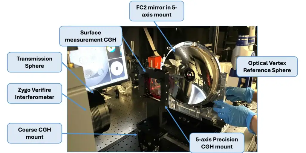
Fig. 3 — Checking the damaged mirror: FC2 in its five-axis mount, measured through the surface CGH with a Zygo Verifire interferometer. Image: Agarwal et al., JATIS (2025).
CGH #2: Aligning the Two Mirrors
The second CGH showcases this method’s power and speed (Figure 4). A single 6-inch substrate, positioned in the converging space between FC1 and FC2, carries three concentric pattern zones. A central circle and four spokes retro-reflect the interferometer beam to position the CGH to the input beam. An inner annulus shapes light to retro-reflect from FC1’s convex hyperboloid. An outer annulus does the same for FC2’s concave ellipsoid.
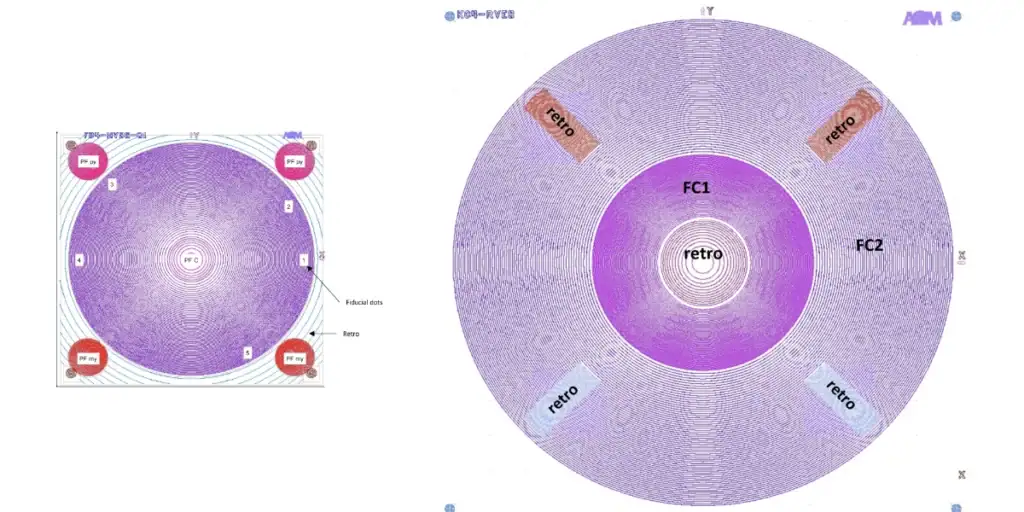
Fig. 4 — The two CGH designs. Left: the surface-measurement CGH, with corner fiducial projectors, a central vertex reference, and an annular null for FC2. Right: the alignment CGH, with concentric zones serving the CGH alignment reference (center and spokes), FC1 (inner annulus), and FC2 (outer annulus). Image: Agarwal et al., JATIS (2025).
The result is one test setup that measures the position and orientation of both flight optics simultaneously, each against a common, self-registered reference. When the system is adjusted such that every hologram returns a null, the system is aligned!
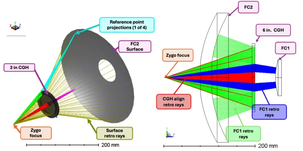
Fig. 5 — How the light travels. Left: the surface test reshapes the f/1.5 beam to match FC2. Right: the alignment test — separate patterns on one substrate send retro-reflecting beams to FC1 (blue), FC2 (green), and back to the interferometer for CGH alignment (red), all at once. Image: Agarwal et al., JATIS (2025).
06 — IN THE LAB
Alignment by the Numbers Rather than “Feel”
With the CGH registered to the Zygo interferometer, aligning the mirrors became a deterministic loop rather than an art. Each optic’s interferogram was measured with phase-shifting interferometry and decomposed into Zernike coefficients — the standard vocabulary of optical aberrations. Because AOM’s design process models the exact amount of wavefront error that each micron of decenter or arcsecond of tilt produces, those coefficients convert directly into physical corrections, allowing the team to easily adjust the system, re-measure, and converge on the aligned positions.
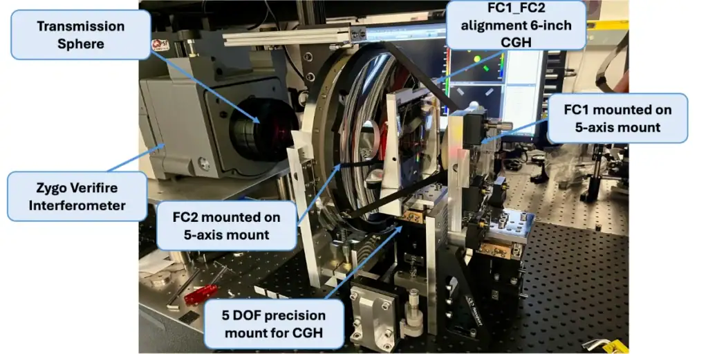
Fig. 6 — The alignment station: Zygo interferometer and transmission sphere at left, the 6-inch CGH on a five-degree-of-freedom mount at center, and both flight mirrors on precision stages. Image: Agarwal et al., JATIS (2025).
The same test setup for alignment also allowed the team to verify performance. After the first bonding attempt, releasing the assembly from its ground-support fixtures revealed that FC1 had shifted beyond tolerance. The stressed flexures had relaxed and pulled the mirror with them. With a conventional imaging test, diagnosing that could have consumed weeks. Here, the CGH measurement flagged the issue immediately and quantified exactly how far each mirror had moved. The team debonded the optic, swapped in spare flexures, the installation, and realigned. The second attempt held position and was successful.
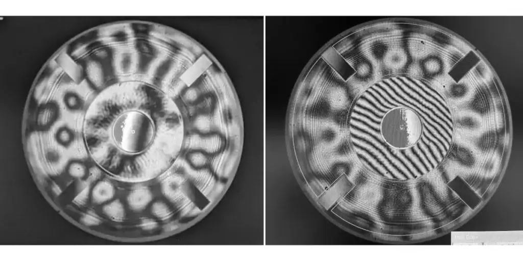
Fig. 7 — What the measurement looks like: interferograms before bonding (left) and after release from the fixtures (right). Each concentric zone is a separate, simultaneous measurement — the two mirrors’ returns in the annular regions. Agarwal et al., JATIS (2025).
The measurement also settled a subtler question. A small residual decenter appeared after the optic was released (Figure 7). However, when the assembly was rotated about its optical axis, the offset stayed fixed in the same orientation. That signature identified it as gravity sag in a flexure rather than a bonding error, and since the corrector flies with gravity along its optical axis, it was harmless. The ability to measure the optic positions directly enabled the team to make this kind of diagnosis quickly. That’s the kind of diagnosis you can only make when your test measures positions directly.
07 — RESULTS
Better Aligned than the Day it was Built
The finished assembly met every requirement, with residual lateral errors within the 25-micron tolerance and relative tilts around a tenth of an arcminute — ten times better than the requirement. Alignment was monitored continuously through the seven-day epoxy cure and re-verified in multiple orientations.
As an independent cross-check, the team repeated the classic pinhole imaging test and compared the result against the same measurement from 2017 (Figure 8). The CGH-aligned system produced an image spot roughly half the width of the original and visibly more symmetric, with the coma and astigmatism that had the original alignment when the system was manufactured.
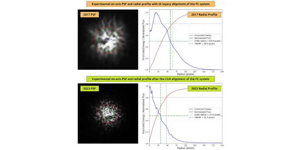
Fig. 8 — Before and after: the on-axis image of a 5-micron pinhole through the focal corrector, as aligned by the legacy process for the 2017 campaign (top) and by the CGH process for 2023 (bottom). The 2023 spot is roughly half the width and far more symmetric. Image: Agarwal et al., JATIS (2025).
08 — TAKEAWAYS
Why Align with CGHs
AOM’s CGH alignment technology has been an essential part of dozens of programs. While most of the alignment systems that AOM builds are proprietary to the programs they serve, FIREBall-2 offers a rare chance to showcase the details of a customer test. The advantages demonstrated by this project apply in most cases:
Direct measurement — CGH-based testing reports the actual position of each optic, instead of inferring alignment from downstream image quality. The system reports misalignments that can be corrected in real time, rather than waiting for them to appear as symptoms in the final image quality.
One substrate, many functions — Nulls for multiple optics, CGH alignment retros, and projected fiducials can share a single hologram, with near perfect co-registration to each other and at minimal added fabrication cost.
Speed — Design and fabrication in weeks, versus months for a conventional null lens. The deterministic alignment loop compresses lab time just as dramatically. The whole FIREBall-2 realignment process was completed within four months.
Non-contact — Nothing in the testing process touches the sensitive optical surfaces and coatings.
Built-in verification — The alignment test doubles as a monitoring and diagnostic tool through epoxy cures, after fixture release, in any orientation. Any shift is immediately apparent, and by quantifiable amounts.
Works with your hardware — The CGH is designed around the interferometer, ubiquitous in the optics industry, and often with the reference accessories you already own
Have a System that Requires Precision Alignment?
Arizona Optical Metrology designs and fabricates custom computer-generated holograms for the measurement and alignment of aspheres, freeforms, and multi-element optical systems — from single-surface figure verification to full alignment stations like the one described here. If your program has tight tolerances and a tighter schedule, we’d like to hear about it. Visit aom.us or contact our team.